Do you have a question about the Atmel SAMA5D3 EK Series and is the answer not in the manual?
Warning regarding ESD sensitivity and proper handling procedures for the evaluation kit to prevent damage.
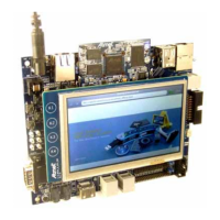
Steps to connect and power on the evaluation board, including expected initial display.
Information on obtaining sample code and technical support from the Atmel web site.
Overview of the SAMA5D3 series evaluation kit as a full-featured platform for microcontrollers.
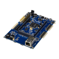
Detailed description of the CPU module (CM) board as the heart of the SAMA5D3x-EK system.
List of key devices and components included on the CPU module board.
Details on the SODIMM200 card edge interface for connecting the CM board.
Description of configuration items like jumpers for setting up the CM board.
Details on the ARM-based embedded MPU (SAMA5D3 series) used in the CM board.
Description of the three clock sources integrated into the CM board.
Information on the different reset sources available for the CM board.
List of schematics available for the CPU Module manufactured by Embest/Flextronics, Revision D.
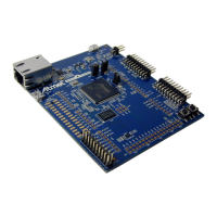
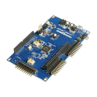
Overview of the SAMA5D3 series main board (MB), its features and interfaces.
Details on the SAMA5D3 series processor and its compatibility with the main board.
Instructions for disabling the J-Link-OB-ATSAM3U4C JTAG functionality via jumper JP15.
Enabling the debug serial port (DBGU) via CDC over USB, controlled by jumper JP16.
Description of the USART1 port for RS-232 serial communication via DB-9 connector.
Description of the reset pushbutton (BP1) and its function for board reset.
Pinout description for the LCD Socket J21 HE10 connector.
Pinout description for the LCD/TSC Socket J22 HE10 connector.
Pinout description for the ISI Socket J11 HE10 connector.
Details of the Power Supply Connector J4, including pinout and signal description.
Signal descriptions for the USB Host/Device MicroAB Connector J20.
Signal descriptions for the USB JTAG OB MicroAB connector J14.
| Operating Frequency | 536 MHz |
|---|---|
| RAM | 256 MB DDR2 |
| Flash Memory | 256 MB NAND Flash |
| Storage | microSD card slot |
| Power Supply | 5V DC |
| Operating Temperature | 0°C to +70°C |
| Core Architecture | ARM Cortex-A5 |
| Ethernet | 10/100 Mbps |
| Serial Ports | UART, SPI, I2C |