74
SAMA5D3x-EK User Guide [USER GUIDE]
11180B–ATARM–29-Oct-13
5.3 Configuration
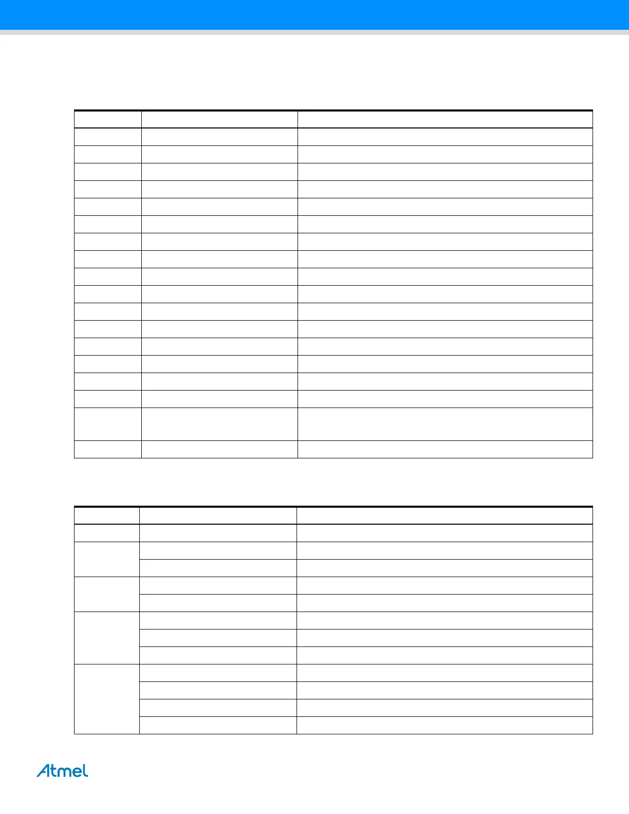
Table 5-2 describes the PIO usage, the jumpers, the test points and the solder drops of a SAMA5D3 series EK board.
Table 5-2. Jumpers and Solderdrops
Reference Default Function
JP1 1-2 VDDIOP0 or 5V selection for J1
JP2 1-2 VDDIOP0 or 5V selection for J2
JP3 1-2 VDDIOP0 or 5V selection for J3
JP4 CLOSE Backup supply on/off
JP5 CLOSE Force power on function
JP6 CLOSE MCI0 write protect select
JP7 CLOSE CAN0 diff termination select
JP8 CLOSE CAN1 diff termination select
JP9 OPEN Default boot on embedded ROM, close boot on external memory
JP10 OPEN ZigBee power on/off select
JP11 —
JP12 —
JP13 —
JP14 1-2 ADVREF input selection
JP15 OPEN JTAG enable
JP16 OPEN CDC enable
JP17
OPEN
CLOSE
Enable LCD for D31, D33, D34
Disable LCD for D35
JP18 1-2 SAM3U powered by main 3V3
Table 5-3. Default Not Populated Parts
Page Reference Function
3 R6,R51,R50,R120 Optional PD10, PD11, PD12, PD13 from MB
5
R58 Optional for MCI0 power supply mode
R121 Optional for MCI1 power supply mode
6
R52,R53,R55,R56,R57,R82,JP10 Optional ZigBee
R132,R133 Debug or USART1 option
7
C89,C90,R118,R119,J26 Optional Audio Line out, MIC in
R80,R81 Optional MIC level setting
R230 Optional audio TK
9
L38,L39,L40,L41 Optional HDMI EMI filter
R89 HDMI chip I2C address setting
R266 Optional for I2S PCLK
R42 Optional for LCD PCLK
 Loading...