13
SAMA5D3x-EK User Guide [USER GUIDE]
11180B–ATARM–29-Oct-13
4.3.4 Power Supplies
The CM board is driven by +3.3V input power rail from the MB through the SODIMM200 connector. The CM board
embeds all necessary power rails required for the microprocessor.
When additional voltages are required, they are generated on-board from the 3.3V supply (power source is a linear
regulator or a switching regulator). The detailed power supply requirements for given modules are specified within the
corresponding product documentation.
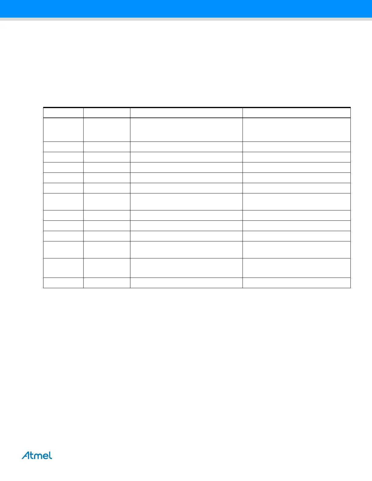
Table 4-5 summarizes the power specifications.
Table 4-5. Supply Group Configuration
Nominal Name Powers Component
3.0V VDDBU
the Slow Clock oscillator, the internal 32K
RC, the internal 12M RC and a part of the
System Controller
From VBAT 3V, SODIMM200 connector
3.3V VDDIOP0 a part of peripheral I/O lines From main 3.3V, SODIMM200 connector
3.3V VDDIOP1 a part of peripheral I/O lines From main 3.3V, SODIMM200 connector
3.3V VDDUTMII the USB device and host UTMI + interface From main 3.3V, SODIMM200 connector
3.3V VDDOSC the main oscillator cells From main 3.3V, SODIMM200 connector
3.3V VDDANA the analog-to-digital converter From main 3.3V, SODIMM200 connector
1.2V VDDCORE
the core, including the processor, the
embedded memories and the peripherals
Regulator on-board
1.2V VDDUTMIC the USB device and host UTMI + core Regulator on-board
1.2V VDDPLLA the PLLA cell Regulator on-board
1.8V VDDIODDR DDR2 interface I/O lines Regulator on-board
1.8V VDDIOM
NAND, NOR Flash and SMC interface I/O
lines
Regulator on-board
3.0V to
3.3V
ADVREF ADC reference voltage From ADVREF, SODIMM200 connector
2.5V VDDFUSE Fuse box for programming Regulator on-board
 Loading...