EasyManua.ls Logo

Atmel ATtiny85 User Manual

Atmel ATtiny85
196 pages
To Next Page IconTo Next Page
To Previous Page IconTo Previous Page
Page #80 background imageLoading...
Page #80 background image
80
7598H–AVR–07/09
ATtiny25/45/85
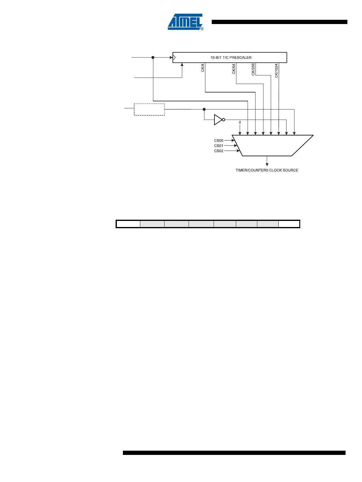
Figure 13-2. Prescaler for Timer/Counter0
Note: 1. The synchronization logic on the input pins (T0) is shown in Figure 13-1.
13.2.1 General Timer/Counter Control Register – GTCCR
Bit 7 – TSM: Timer/Counter Synchronization Mode
Writing the TSM bit to one activates the Timer/Counter Synchronization mode. In this mode, the
value that is written to the PSR0 bit is kept, hence keeping the Prescaler Reset signal asserted.
This ensures that the Timer/Counter is halted and can be configured without the risk of advanc-
ing during configuration. When the TSM bit is written to zero, the PSR0 bit is cleared by
hardware, and the Timer/Counter start counting.
Bit 0 – PSR0: Prescaler Reset Timer/Counter0
When this bit is one, the Timer/Counter0 prescaler will be Reset. This bit is normally cleared
immediately by hardware, except if the TSM bit is set.
PSR10
Clear
clk
T0
T0
clk
I/O
Synchronization
Bit 7 6 5 4 3 2 1 0
TSM
PWM1B COM1B1 COM1B0 FOC1B FOC1A PSR1 PSR0 GTCCR
Read/Write R/W R R R R R R R/W
Initial Value 0 0 0 0 0 0 0 0

Table of Contents

Question and Answer IconNeed help?

Do you have a question about the Atmel ATtiny85 and is the answer not in the manual?

Atmel ATtiny85 Specifications

General IconGeneral
Architecture8-bit AVR
Flash Memory8 KB
SRAM512 B
EEPROM512 B
Clock Speed20 MHz
GPIO Pins6
ADC Channels4
ADC Resolution10-bit
Timers2 (8-bit)
PWM Channels2
Operating Voltage2.7V - 5.5V
Communication InterfacesSPI, I2C
PackageDIP-8, SOIC-8
Operating Temperature-40°C to 85°C

Summary

ATtiny25/45/85 Features Overview

High-Performance AVR Microcontroller

Details on the advanced RISC architecture and its benefits for performance.

Non-volatile Program and Data Memories

Information on Flash, EEPROM, and SRAM capacities and endurance.

Peripheral Features

Overview of integrated peripherals like Timers, ADC, and USI.

ATtiny25/45/85 Pin Configuration

ATtiny25/45/85 Block Diagram

ATtiny25/45/85 Pin Descriptions

AVR CPU Core

Architectural Overview

Explanation of the Harvard architecture and pipelining.

Reset and Interrupt Handling

Explanation of reset sources and interrupt vector handling.

AVR ATtiny25/45/85 Memories

In-System Re-programmable Flash Program Memory

Details on Flash memory size, endurance, and programming.

SRAM Data Memory Organization

Description of SRAM organization and addressing modes.

EEPROM Data Memory

Information on EEPROM capacity, endurance, and access.

System Clock and Clock Options

System Clock Prescaler

Explanation of the Clock Prescale Register (CLKPR) for clock frequency control.

Power Management and Sleep Modes

Minimizing Power Consumption

Strategies for reducing power consumption in the device.

System Control and Reset

Reset Sources

Overview of the four reset sources: Power-on, External, Watchdog, Brown-out.

Power-on Reset (POR)

Details on the POR circuit, detection level, and start-up timing.

Brown-out Detection (BOD)

Information on the on-chip BOD circuit and selectable trigger levels.

Watchdog Timer

Details on the Watchdog Timer operation, configuration, and reset.

Interrupts

I/O Ports

External Interrupts

8-bit Timer/Counter0 with PWM

Modes of Operation

Explanation of Normal, CTC, Fast PWM, and Phase Correct PWM modes.

Counter and Compare Units

Timer/Counter1 in PWM Mode

Details on generating PWM waveforms with Timer/Counter1.

Universal Serial Interface (USI)

Analog Comparator

Analog to Digital Converter (ADC)

ADC Features

Overview of ADC resolution, conversion time, and input channels.

ADC Operation

Explanation of the ADC conversion process and voltage references.

Starting a Conversion

Methods for initiating ADC conversions, including auto-triggering.

ADC Conversion Result

Details on how the conversion result is presented and interpreted.

debugWIRE On-chip Debug System

Self-Programming the Flash

Memory Programming

High-voltage Serial Programming

Procedures for programming Flash, EEPROM, Lock bits, and Fuses.

Electrical Characteristics

Related product manuals