23
7598H–AVR–07/09
ATtiny25/45/85
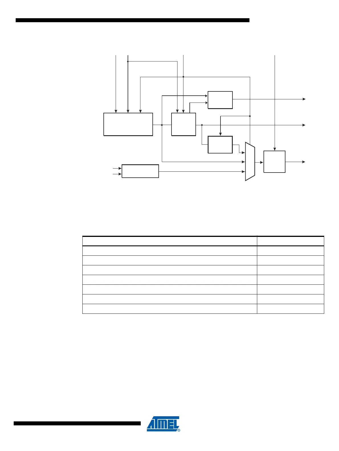
Figure 6-2. PCK Clocking System
6.2 Clock Sources
The device has the following clock source options, selectable by Flash Fuse bits as shown
below. The clock from the selected source is input to the AVR clock generator, and routed to the
appropriate modules.
Note: 1. For all fuses “1” means unprogrammed while “0” means programmed.
The various choices for each clocking option is given in the following sections. When the CPU
wakes up from Power-down or Power-save, the selected clock source is used to time the
start-up, ensuring stable Oscillator operation before instruction execution starts. When the CPU
starts from reset, there is an additional delay allowing the power to reach a stable level before
commencing normal operation. The Watchdog Oscillator is used for timing this real-time part of
the start-up time. The number of WDT Oscillator cycles used for each time-out is shown in Table
6-2.
8.0 MHz / 6.4 MHz
RC OSCILLATOR
OSCCAL
XTAL1
XTAL2
OSCILLATORS
DIVIDE
BY 4
SYSTEM
CLOCK
PLL
8x / 4x
PLLCK & CKSEL FUSES
PLLE
PCK
Lock
Detector
PLOCK
64 / 25.6 MHz
System
Clock
Prescaler
CLKPS3..0
Table 6-1. Device Clocking Options Select
(1)
Device Clocking Option CKSEL3..0
External Clock 0000
PLL Clock 0001
Calibrated Internal RC Oscillator 8.0 MHz 0010
Watchdog Oscillator 128 kHz 0100
External Low-frequency Crystal 0110
External Crystal/Ceramic Resonator 1000-1111
Reserved 0101, 0111, 0011