T
Tony WatersAug 2, 2025
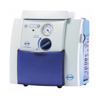
What to do if there is an alarm during suction application with Atmos Atmoforte 350 Medical Equipment?
- RRobert SmithAug 2, 2025
If you get an alarm during suction with Atmos Medical Equipment, and the collection jar is full, the bacterial filter is clogged, there's excessive foam, or the unit's contacts are contaminated, here's what to do: * Empty the collection jar. * Clean or replace the filter. * Install foam protection. * Clean the contact bar.