ATS Systems Ultimate Chuck Installation and Operations Manual
INSTALLATION:
3.1 Installing the chuck to the machine
spindle
See 6.1 in OTHER INFO section of this manual for
parts identification.
3.1.1 Checking the chuck and machine spindle
• Check the machine’s spindle nose and flange, or
the finished machined adapter plate concentricity
and face runout. Maximum allowable runouts are
0.005 mm.
• All mating surfaces must be clean and free of
nicks, dents, chips, dirt, etc.
3.1.2 Installing the chuck
• Remove the chuck from the package, check for
damage and that it is complete.
• If there are any base jaws installed in the chuck,
unlock and remove them. (see this manual
section 4.1).
• You need to determine the actual maximum
stroke of your hydraulic cylinder and drawtube.
Actuate the cylinder and extend the drawtube
fully forward. Using calipers, measure from the
end of the lathe spindle nose to the front of the
drawtube and record the dimension. Now
actuate the cylinder and fully retract the
drawtube and record the measurement from the
same point on the spindle nose to the same point
on the end of the drawtube. Subtract these two
numbers and record here the actual drawtube
stroke for future reference.
Cylinder stroke = ___________
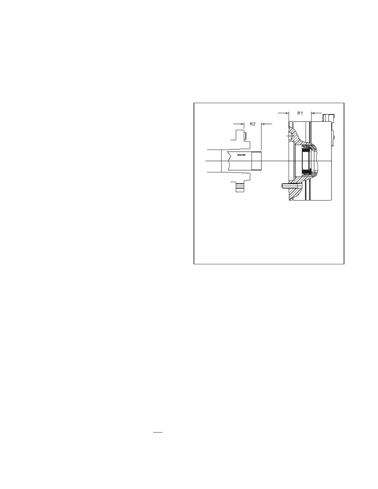
• Actuate the cylinder so that the
drawbar/drawtube once again extends fully
forward. (see figure 3.1).
• Push the chuck piston into its forward most
position.
• Confirm R2 dimension is .010" - .080" less than
R1 dimension measured to the inside bottom of
the drawtube adapter. If R2 is not shorter than
R1 STOP and rework the drawtube adapter if
possible or shorten the drawtube.
• Use supplied T-wrench (60) to tighten drawtube
adapter retaining ring (5) with drawtube adapter
(4) in place in chuck. Confirm drawtube adapter
is free to rotate but has less than .008" of end
play (allowable drawtube Z axis free motion).
Rework drawtube adapter if necessary. Remove
drawtube adapter retaining ring and remove
drawtube adapter. Screw drawtube adapter fully
onto drawtube to confirm tread fit.
• Put a small amount of never-seize or grease on
the front and the rear of the drawtube adapter
flange (not on the threads). Put the drawtube
adapter into the chuck keeping the never-seize
off of the threads. Install drawtube adapter
retaining ring with several drops of thread-locker
and tighten retaining ring with T-wrench. (Don't
use excessive thread-locker.)
Actuate lathe cylinder to push drawtube to
forward most position.
R1 = Push the chuck piston fully forward
and measure with a depth gauge.
R2 = R1 – 0.01" (max .080")
Fig 3.1
 Loading...