Note: The optics must be kept clean, and all dust must be removed before use. If
the welding head is to insert the optical fiber vertically, the welding head must be
rotated 90 degrees to a horizontal position, and then insert the optical fiber to
prevent dust from entering the interface and falling on the surface of the lens. Fix
the laser head after inserting the optical fiber.
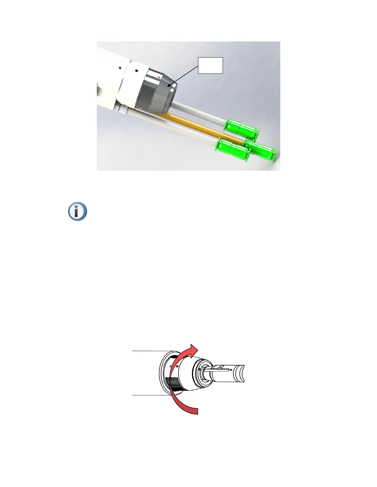
Fiber rod insertion and locking
First, align the red dots on the end face of the QBH interface with the red dots of
the rotating handwheel; then, remove the QBH dust cap, align the red mark of the fiber
output end with the QBH red mark, and insert it straight to the bottom; next, rotate the
QBH hand wheel clockwise to reach the right position when hearing the sound of "Da",
then pull the handwheel upwards and turn it clockwise to the end again. As shown in
Figure 6 below.
Figure 6 HW970 QBH fiber rod insertion and locking diagram