Step 3:
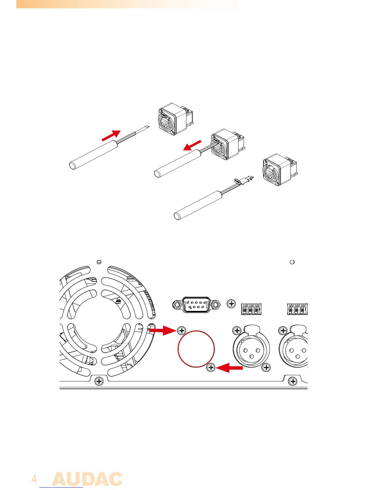
3.1. Remove the latch from the Ethercon compatible connector on the connection board
by putting a flat screwdriver underneath the clip and pulling back screwdriver and latch
together. This will simplify the assembly of the ethernet connection board in the back
of the unit.
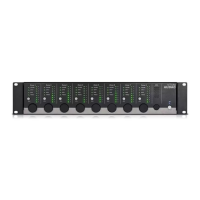
3.2. Remove the cover plate at the ‘EXPANSION’ hole on the back of the amplifier. The
ethernet connection board of the ANIxx shall be installed on this position.
3.3. Insert the ethernet connection board from the inner side of the amplifier to the
‘EXPANSION’ hole, and fix it by inserting and tightening the two supplied screws. The
latch removed from the connector in step 3.1 can now get inserted to the connector
again by simply inserting and pushing it into the right position.