Chapter 1
Pin connections and connectors
CONNECTION STANDARDS
The in- and output connections for AUDAC audio equipment are performed corresponding to international
wiring standards for professional audio equipment.
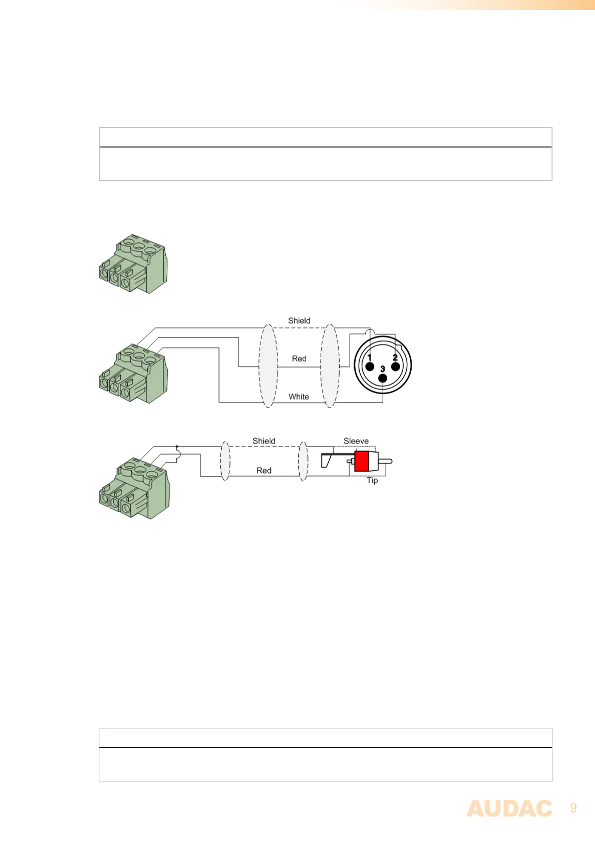
3-Pin Terminal Block:
For balanced in & output connections
Left: Signal - (XLR Pin 3)
Center: Signal + (XLR Pin 2)
Right: Ground (XLR Pin 1)
For balanced line output connections:
For unbalanced line output connections:
RS232 (serial connection interface):
For connection with home automation systems, or other remote control equipment
Connection Standard RS232
PIN 2 DSP40 TX
PIN 3 DSP40 RX
PIN 5 GND
Settings 19200 Baud
8 Bit
1 Stop bit
No parity
No Handshaking
RS232
The complete command set for controlling the DSP40 through RS-232 is available in the DSP40
commands user manual which is freely downloadable on www.audac.eu