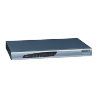
3 MP-124 Ports
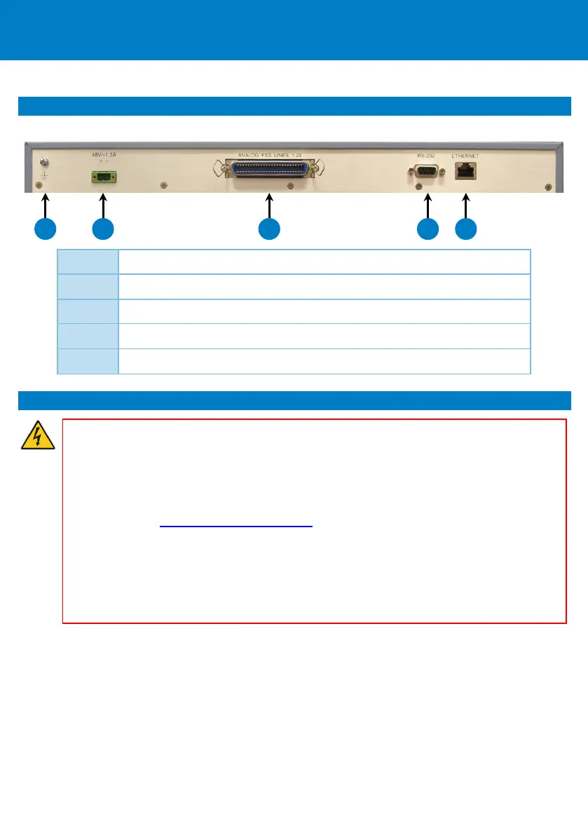
MP-124 provides ports on its rear-panel, a s shown below a nd described in the s ubsequent ta ble.
1 Grounding lug
2 DC powe r inlet
3 50-pin female Telco connector, s upporting up to 24 FXS i nterfaces
4 DB-9 pi n female connector for RS-232 serial interface
5 RJ-45 Etherne t port (10/100BaseTX)
4 Cabling and Installing MP-124
Warnings:
• Prior to installing MP-124, proper grounding (earthing) and power-surge protection mus t
be done; refer to the Hardware Installation Manual for detailed instructions. AudioCodes'
will not bear responsibility to damage that may be ca used to the device a s a result of not
complying with the instructions detailed i n the Hardware Installation Manual.
• Prior to connecting MP-124 to power, refer to the Compliancy and Regulatory Information
document at www.audiocodes.com/library
.
• Connect MP-124 to a s afety extra-low voltage (SELV) source that is sufficiently isolated
from the mains.
• For FXS cabling, you ca n use your own third-party MDF connector cable or you ca n use
AudioCodes' MP-124 FXS Pa tch Pa nel (ordered s eparately from AudioCodes). When using a
thi rd-party MDF for FXS ca bling, to re duce noise i nterference, use a twisted-pair Octopus
cable terminated on a metal-hooded 50-pin Te lco connector.
To cable and install MP-124:
1. Connect the Ethernet port to your LAN switch, using the RJ-45 Ethernet cable connector.
2. Connect MP-124 to FXS-based analog equipment (for example, telephone, fax, a nd modem):
• Third-party MDF: Us ing a twisted 25-pair Octopus ca ble, connect e ach wire pair to i ts corresponding
MDF adaptor block socket, and then connect the wire-pairs a t the other end to a 50-pin male Telco
connector. Connect this to the MP-124 50-pi n female Telco connector. Con nect your analog
equipment to the MDF using RJ-11 cables.