Do you have a question about the Audiotec Fischer match M 5.4DSP and is the answer not in the manual?
Guidance on safely installing the amplifier, including precautions against damage and injury.
Instructions on connecting the amplifier, including voltage requirements and cable usage.
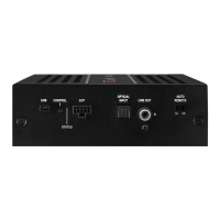
Main connection port and switch for automatic amplifier turn-on.
Ports for remote signal input/output and passive subwoofer connection.
Ports for PC connection, digital audio input, and accessory control.
Controls setup switching and device reset; LED indicates operating status.
Detailed explanation of signal input, output, and power for the system connector.
How Auto Remote and Remote In/Out control amplifier power-up.
Connecting subwoofers and using the USB input for amplifier configuration.
Managing sound setups and performing a device reset.
Understanding the meaning of different LED colors for amplifier status.
Using pre-amplifier outputs to connect additional power amplifiers.
Connecting digital audio sources and accessory devices via SCP.
Diagnosing issues based on red/green flashing patterns of the Status LED.
Explains the two power modes: HighPower for performance, MidPower for Plug & Play.
Step-by-step guide to enable HighPower mode via DSP PC-Tool software.
Conditions for HighPower, including direct battery connection and potential hazards.
Detailed pinout diagram and description for the system connector.
Description of the included subwoofer connection cable and its connectors.
Details on the cable for connecting additional amplifiers via RCA.
How to connect highlevel speaker inputs from head units to the amplifier.
Connecting amplifier outputs to the vehicle's loudspeakers, ensuring correct polarity.
Using the optical input for digital audio and its volume control considerations.
Mandatory step to match input sensitivity to the signal source to prevent damage.
Using DSP PC-Tool to adjust input gain and avoid clipping.
Detailed instructions for connecting the power supply directly to the battery.
Connecting the remote input for amplifier turn-on signal.
Importance of initial DSP configuration before first use to prevent damage.
Connecting passive subwoofers or speakers to the dedicated subwoofer output.
Using pre-amplifier outputs to connect additional amplifiers.
Using the remote output signal to turn on external amplifiers.
Steps for connecting the amplifier using a PP-ISO cable harness to an OEM radio.
Explains the two power supply options, emphasizing direct battery connection for HighPower.
Detailed steps for direct battery connection, including wire gauge and fusing.
Identifying and connecting permanent plus and switched plus terminals for power.
Specific instructions for cars equipped with MOST bus structures.
Diagram illustrating direct power supply connection to the car's battery for HighPower mode.
Details on connecting yellow (+12V) and black (ground) wires to the battery.
Instructions on downloading and installing the necessary PC software for configuration.
Steps for connecting the amplifier to the PC via USB and initial software startup.
Recommendations for safe initial setup, including radio volume and output connections.
Illustrates a 5-channel MidPower configuration without Virtual Channel Processing.
DSP PC-Tool screenshot showing channel routing for the 5-channel MidPower setup.
Illustrates a 5-channel HighPower configuration without Virtual Channel Processing.
DSP PC-Tool screenshot showing channel routing for the 5-channel HighPower setup.
Illustrates a 7-channel HighPower setup with an additional amplifier.
DSP PC-Tool routing for the 7-channel setup using Virtual Channel Processing.
Example of connecting BMW under-seat subwoofers.
Example of connecting Mercedes front subwoofers.
Diagram showing virtual channel routing for specific subwoofer configurations.
Explains VCP as a multi-stage signal processing concept for complex sound systems.
Lists benefits of VCP, including cross-channel EQ and multi-way speaker configuration.
How group EQ on virtual channels affects multiple output channels simultaneously.
Applying DSP effects like RealCenter to virtual channels for flexible speaker setups.
Using virtual channels for features like Rear Attenuation, controllable via remote.
Routing input signals to the respective virtual channels in the DSP PC-Tool.
Assigning specific input signals like "front left" to virtual channels.
Assigning configured virtual channels to physical output channels.
Linking virtual signals to physical outputs, allowing multiple assignments.
Configuring virtual channels and applying DSP sound effects like RealCenter.
Steps for setting up center speaker processing using RealCenter and ClarityXpander.
Routing the Virtual E channel to output channels for center processing.
Configuring bass enhancement features like Dynamic Bass Enhancement and SubXpander.
Enabling and configuring the subwoofer remote control in DSP PC-Tool.
How subwoofer remote control is tied to output channels with and without VCP.
Setting delay times for amplifier switching to prevent noises.
Managing ten memory locations for sound setups using remote controls.
Controlling temporary deactivation of remote output during sound setup switches.
Adapting the ADEP.3 circuit for OEM radio diagnostic compatibility.
High efficiency amplifier concept with variable supply voltage for reduced heat.
Powerful co-processor for monitoring, communication, and software upgrades.
Maintains stable internal voltage even during engine cranking.
Circuit to prevent issues with modern car radio diagnostic systems.
Detailed RMS output power ratings for channels and subwoofer in different modes.
Lists input sensitivity, impedance, and output voltage for various connections.
Covers frequency response, DSP power, signal-to-noise ratio, and operating voltage.
Physical dimensions and crucial fuse rating information (30 A).
| Channels | 4 |
|---|---|
| Amplifier Class | Class D |
| DSP resolution | 64 Bit |
| DSP power | 295 MHz |
| Input impedance | 13 kOhms |
| Built-in DSP | Yes |
| Signal-to-noise ratio digital input | > 100dB |
| Fuse | 25A |
| Additional features | Start-Stop capability |
| Signal-to-Noise Ratio | > 102 dB |