Do you have a question about the Audiotec Fischer Match UP 8DSP and is the answer not in the manual?
Guidelines for safe and correct installation of MATCH components to prevent damage or injury.
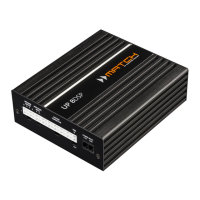
Specifics on connecting the UP 8DSP amplifier, including power and grounding requirements.
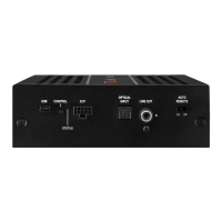
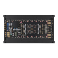
Identifies speaker output terminals E through H on the amplifier.
Identifies highlevel audio input terminals E and F.
Locates the main system connector input for various connections.
Details the remote input/output connectors for power control.
Identifies the power input connector for the amplifier.
Locates the USB input for PC connectivity and software updates.
Identifies the pushbutton for control and setup functions.
Locates the switch for automatic remote turn-on functionality.
Identifies the Smart Control Port for accessory connections.
Locates the digital optical audio input.
Identifies the analog line output for external amplifiers.
Locates the status LED for amplifier operational feedback.
Detailed pin assignments for the main system connector.
Pin assignments for highlevel audio inputs E and F.
Pin assignments for speaker outputs E through H.
Details the connection cable for the system connector.
Details the connection cable for speaker outputs E-H.
Details the connection cable for highlevel inputs E-F.
Details the connection cable for remote signals.
Instructions for connecting the main system connector, including highlevel inputs.
Guide for connecting optional highlevel speaker inputs E and F.
Details on connecting speaker outputs E-H and subwoofers.
Instructions for connecting digital audio sources via optical input.
Setting up the remote input for amplifier turn-on functionality.
Guidance on connecting remote wires for power and control.
Critical steps for connecting the amplifier to the vehicle's power supply.
Steps for connecting the amplifier to a PC for configuration and initial setup.
Procedure for setting input sensitivity for optimal audio performance and safety.
Guide to configuring the amplifier's internal Digital Signal Processor settings.
Using the DSP PC-Tool's Signal Analyzer to check input signal characteristics.
Instructions for connecting the line-level output to an external amplifier.
Explanation of the different states indicated by the status LED.
Details on using the control pushbutton for memory selection and device reset.
Description of the SCP for connecting remote controls and accessories.
Illustrates channel routing using Virtual Channel Processing for a 4-channel head unit.
Demonstrates an 8-channel to 1-channel routing example with subwoofers.
Configures the delay time for amplifier power-on and power-off sequences.
Defines memory locations for switching sound setups via remote control.
Controls temporary deactivation of remote output during setup switches.
Adapts the ADEP.3 circuit for OEM radio compatibility and noise suppression.
| Brand | Audiotec Fischer |
|---|---|
| Model | Match UP 8DSP |
| Category | Amplifier |
| Language | English |