Do you have a question about the Audiotec Fischer Match M 5DSP and is the answer not in the manual?
Guidelines to prevent damage and injury during installation.
Connect M 5DSP to 12V negative terminal systems; use specific cables.
Connects amplifier to MATCH cable harness; use original cable.
Activates/deactivates automatic turn-on feature for amplifier.
Stereo pre-amp output for external amplifiers; use Remote Out for turn-on.
Connector for passive subwoofer; use provided subwoofer cable.
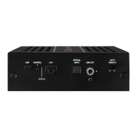
Connects M 5DSP to PC for software configuration and updates.
Switches between setups or initiates device reset.
Input for amplifier turn-on; output for additional amplifiers.
Indicates amplifier operational status, setup, and protection modes.
Input for digital stereo signals (SPDIF format).
Interface for optional remote controls or accessories.
Use only specified cables; HighPower mode requires specific harness.
Automatic turn-on via highlevel input or Remote In; disable for noise.
3.5mm output for power amps; use Remote Out, avoid ignition switch control.
Connect passive subwoofers; recommend direct +12V power for subwoofers.
Connect to PC using USB; download and install DSP PC-Tool software.
Select HighPower for maximum performance or MidPower for low consumption.
Steps to activate HighPower mode via DSP PC-Tool software (irreversible).
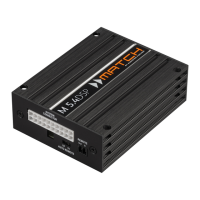
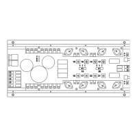
Diagram and list of pin assignments for the system connector.
Illustrates the subwoofer connection cable and its connectors.
Connect to OEM/aftermarket radio speaker outputs; polarity is critical.
Connect amplifier outputs to speakers; ensure correct phase and impedance.
Connect optical digital sources; auto-detection or manual control.
Connect +12V and ground to battery; proper wire gauge and fuse are essential.
Connect to signal source remote output for amplifier turn-on.
Use to turn on additional amplifiers connected to Line Out.
Connect passive MATCH Plug & Play or conventional subwoofers.
Simplified installation using PP-ISO cable to OEM radio.
Choose between vehicle harness or direct battery supply.
Direct battery connection is mandatory for HighPower mode.
Diagram showing how to identify permanent and switched plus terminals.
Diagram illustrating direct power supply for HighPower mode operation.
ADEP circuit prevents OE radio errors with sophisticated diagnostics.
HighPower for max performance, MidPower for Plug & Play applications.
Seamless switching between analog and digital inputs.
Reduces power consumption when no signal is detected for a period.
RMS and max output power for channels and subwoofer.
Frequency range, input channels, DSP resolution, and impedance.
THD, S/N ratio, input sensitivity, max remote current, fuse type.
Undervoltage detection, dimensions, and additional features list.
| Channels | 5 |
|---|---|
| Amplifier Class | Class D |
| DSP | Yes |
| DSP Resolution | 64 Bit |
| DSP Power | 295 MHz |
| Number of DSP Channels | 6 |
| Damping factor | >100 |
| Input Impedance | 13 kOhms |
| High-Level Input | Yes |
| Low-Level Input | Yes |
| Frequency Response | 20 Hz - 22, 000 Hz |
| THD+N | <0.05% |
| Total Harmonic Distortion | <0.05% |
| Features | Start-Stop capability |