10
15
ITALIANO
DATI TECNICI
ALIMENTAZIONE 11 ÷ 15 VDC
ASSORBIMENTO A VUOTO 0,8 A
ASSORBIMENTO MAX (Pot. Nominale) 14 A
MAX DYNAMIC POWER (2 Ch x 4 Ohm) 75 W
MAX DYNAMIC POWER (1 Ch x 4 Ohm) Bridge 225 W
POTENZA NOMINALE CONT. (Toll. +10 %; -5 %)
2 Ch x 4 Ohm; 0,3 % THD; 12 VDC 45 W (RMS)
POTENZA OUT CONTINUA (2 Ch x 4 Ohm; 13,8 VDC) 50 W (RMS)
POTENZA OUT CONTINUA (2 Ch x 2 Ohm; 13,8 VDC) 75 W (RMS)
POTENZA OUT MONO (1 Ch x 4 Ohm; 13,8 VDC) Bridge 150 W (RMS)
DISTORSIONE THD (1 KHz; 90% Pot. Nominale) 0,07 %
BANDA PASSANTE (-3 dB; Pot. Nominale) 4 Hz ÷ 100 KHz
FATTORE DI SMORZAMENTO (4 Ohm) 150
TEMPO DI SALITA 4,5 µS
RAPPORTO SEGNALE RUMORE 98 dBA
SENSIBILITA' D'INGRESSO 0,3 V ÷ 4 VRMS
IMPEDENZA D'INGRESSO 15 KOhm
IMPEDENZA DI CARICO Stereo 8 - 4 - 2 Ohm
IMPEDENZA DI CARICO Mono 8 - 4 Ohm
REMOTE IN 7 ÷ 15 VDC
DIMENSIONI (BxAxL) 175 x 50 x 290 mm
ENGLISH
TECHNICAL DATA
POWER SUPPLY 11 ÷ 15 VDC
IDLING CURRENT 0.8 A
MAX CONSUMPTION (Nominal Pwr) 14 A
MAX DYNAMIC POWER (2 Ch x 4 Ohms) 75 W
MAX DYNAMIC POWER (1 Ch x 4 Ohms) Bridge 225 W
CONT. NOMINAL POWER (Tol. +10%; -5%)
2 Ch x 4 Ohms; 0.3% THD; 12 VDC 45 W (RMS)
CONT. OUT POWER (2 Ch x 4 Ohms; 13.8 VDC) 50 W (RMS)
CONT. OUT POWER (2 Ch x 2 Ohms; 13.8 VDC) 75 W (RMS)
MONO OUT POWER (1 Ch x 4 Ohms; 13.8 VDC) Bridge 150 W (RMS)
DISTORTION THD (1 KHz; 90% Nominal Pwr) 0.07 %
BANDWIDTH (-3 dB; Nominal Pwr) 4 Hz ÷ 100 KHz
DAMPING FACTOR (4 Ohms) 150
RISE TIME 4.5 µS
SIGNAL / NOISE RATIO 98 dBA
INPUT SENSITIVITY 0.3 V ÷ 4 VRMS
INPUT IMPEDANCE 15 KOhms
LOAD IMPEDANCE Stereo 8 - 4 - 2 Ohms
LOAD IMPEDANCE Mono 8 - 4 Ohms
REMOTE IN 7 ÷ 15 VDC
DIMENSIONS (WxHxD) 175 x 50 x 290 mm (6.88 x 1.96 x 11.41 inch)
LR 72
LR 72
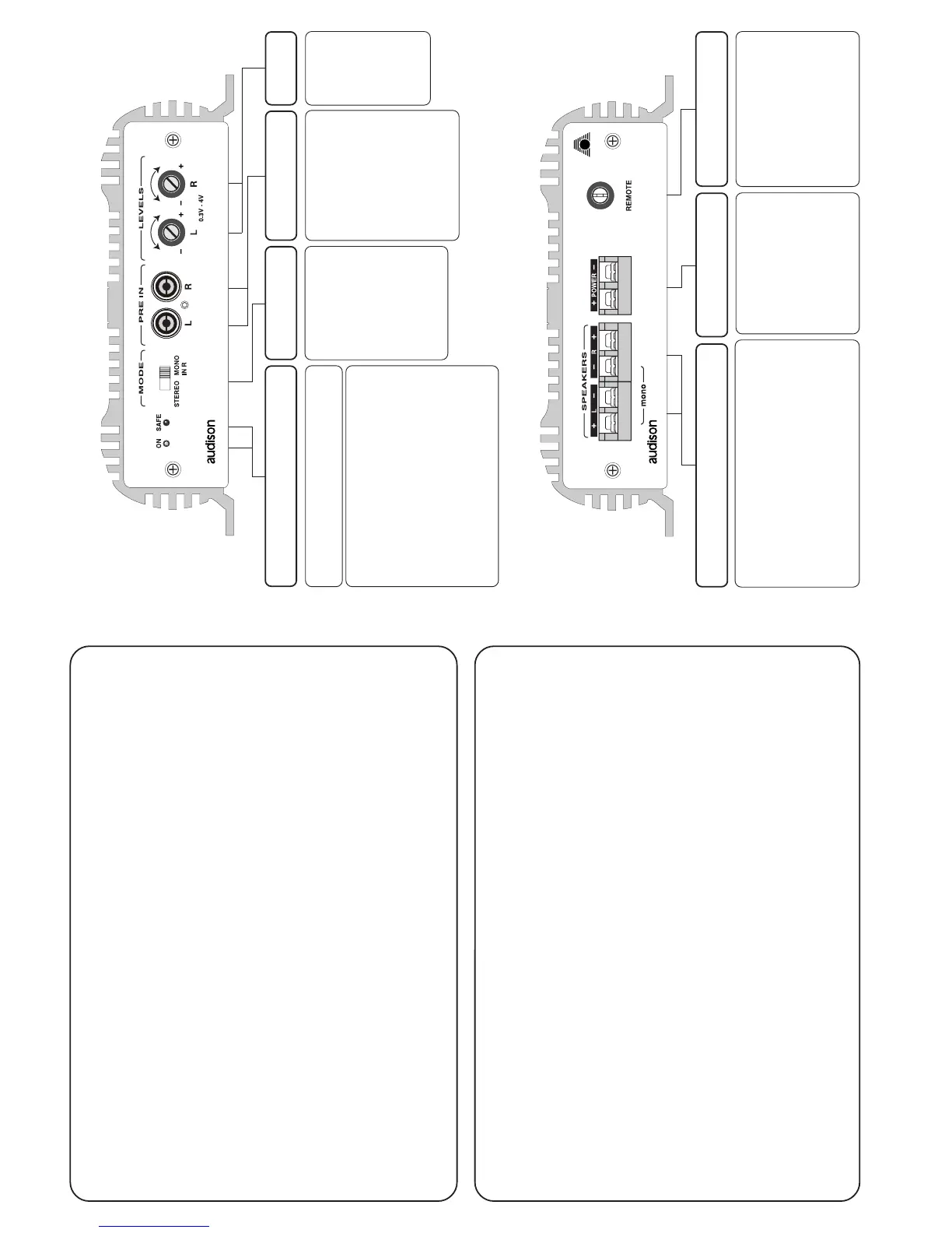
CONFIGURATION OF CONNECTING CLAMPS
CONTROLS AND FUNCTIONS
INDICATORS LIGHTS
SAFE
When lit, it indicates the intervention of pro-
tection circuits: in case of overheating (tempe-
rature exceeding 80° C / 176° F) or output
anomalies (presence of continuous current,
short circuit, or dangerously low load impe-
dance). When protection circuits intervene,
the amplifier shuts down. Turn the amplifier
off. When the problem is corrected, turn the
amplifier back on.
FUNCTION
SELECTION
INPUTS
LEVEL
CONTROLS
POWER
Input clamps for the ampli-
fier power supply.
Connect the battery positi-
ve and negative according
to indicated polarities.
Applied voltage must be
between 11 and 15 VDC.
IN
Turn on control for the ampli-
fier coming from radio-casset-
te player (or from any sources
provided with remote control
for amplifiers).
Applied voltage must be
between 7 and 15 VDC.
OUTPUT CLAMPS
ON
Lit when the amplifier is on.
MODE
STEREO:
The amplifier is se-
lected as stereo.
MONO:
The amplifier si se-
lected as mono.
Right input is used.
PRE IN
Left and Right inputs of the
amplifier.
They can be used to amplify
the PRE output of a signal
source (radio, CD-DAT),
an electronic crossover out-
put or an output of any kind
of signal processor at pre-
amplified level.
LEVELS
Level control
for the ampli-
fier Left and
Right outputs.
Sensitivity
varies from
300 mV to 4 V.
POWER SUPPLY
CLAMPS
REMOTE
L / R
Power outputs for the Left and Right channels of
the amplifier. Connect loudspeakers according to
indicated polarities.
MONO
Outputs for bridge mono configuration. To be
used when the amplifier is selected in MONO IN
R configuration through the switch on the front
side of the amplifier.
 Loading...