5. Description Profibus DP interface
LED ’SYSTEM OK’
(V1)(green)
This LED shows the correct voltage supply to the Profibus DP board.
Is continuously illuminated: Voltage connected to Profibus DP interface.
Is blinking: Microcontroller defective.
Is not illuminated: No voltage at the DP interface.
LED ’DATA EX’ (V2)
(green)
When LED is illuminated, the Profibus DP interface has entered ‘Data
Exchange’ state. Only in this state can the actuator be controlled by the
Profibus DP master and the state of actuator be read.
LED ‘CAN STATE’ (V3)
(red)
Is illuminated or blinking: Communication to logic is faulty
Is not illuminated: Communication with logic is o.k.
LED ’STATE’ (V4)
(green)
Is illuminated or not illuminated: Profibus DP interface is not ready
is blinking: Program on the Profibus DP interface is
being executed.
Regular blinking of the LED during operation indicates correct operation of
the Profibus DP interface.
5.1 Status indications in the
display
The status indications (Group
S) in the display show the current operation
mode as well as faults and warnings. For detailed notes regarding the
indication and operation see the appropriate operation instructions of the
actuator.
Actuator controls AUMATIC AC 01.1 / ACExC 01.1
Short instructions Profibus DP
13
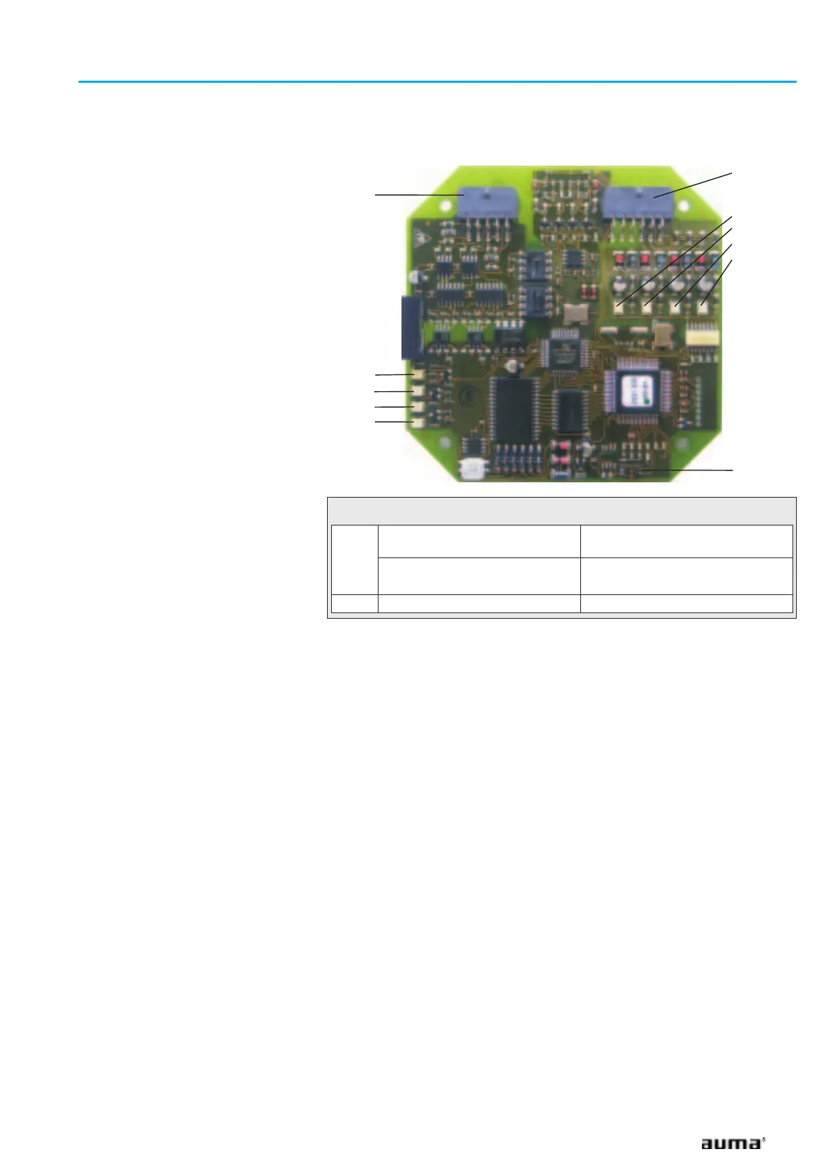
C
Figure P: Profibus DP interface
X2
X4
V16
V19
V22
V25
S1
SYSTEM OK (V1)
DATA EX (V2)
CAN STATE (V3)
STATE (V4)
S1-1
Only one Profibus DP interface
available
OFF
Two Profibus DP interfaces avail-
able
1
st
Profibus DP interface: OFF
2
nd
Profibus DP interface: ON
S1-2 Spare OFF
Table 6: DIP switch S1: Configuration of the Profibus DP board
 Loading...


