46
b) If the voltages are not proper, it means relay failure on the PS card. Replace the PS
card.
XIII. 4-20mA Signal Fail:
TROUBLESHOOT:
a. Check if 4-20mA values in Diagnostic Mode are less than 30 or greater than 2000.
b. Under Remote-regulating duty mode we have to give 4-20mA DC Current
from external DC source to the respective terminals (as per WD) named
with ferrule “II+” and “II-“.
c. Check the connectivity of J5 connector at the Interface Board and also verify
the wiring with respect to WD and ensure that the 4- 20mA input is coming
from DCS.
d. If the 4-20mA values in Diagnostic Mode is correct and a signal fail still occurs, then replace the
IF card.
XIV. Mode selected in Local option is not displaying on the LCD screen: This problem arises
if “Remote Sel. Switch” option is enabled. To disable this option, enter into the
Program Mode – General Settings
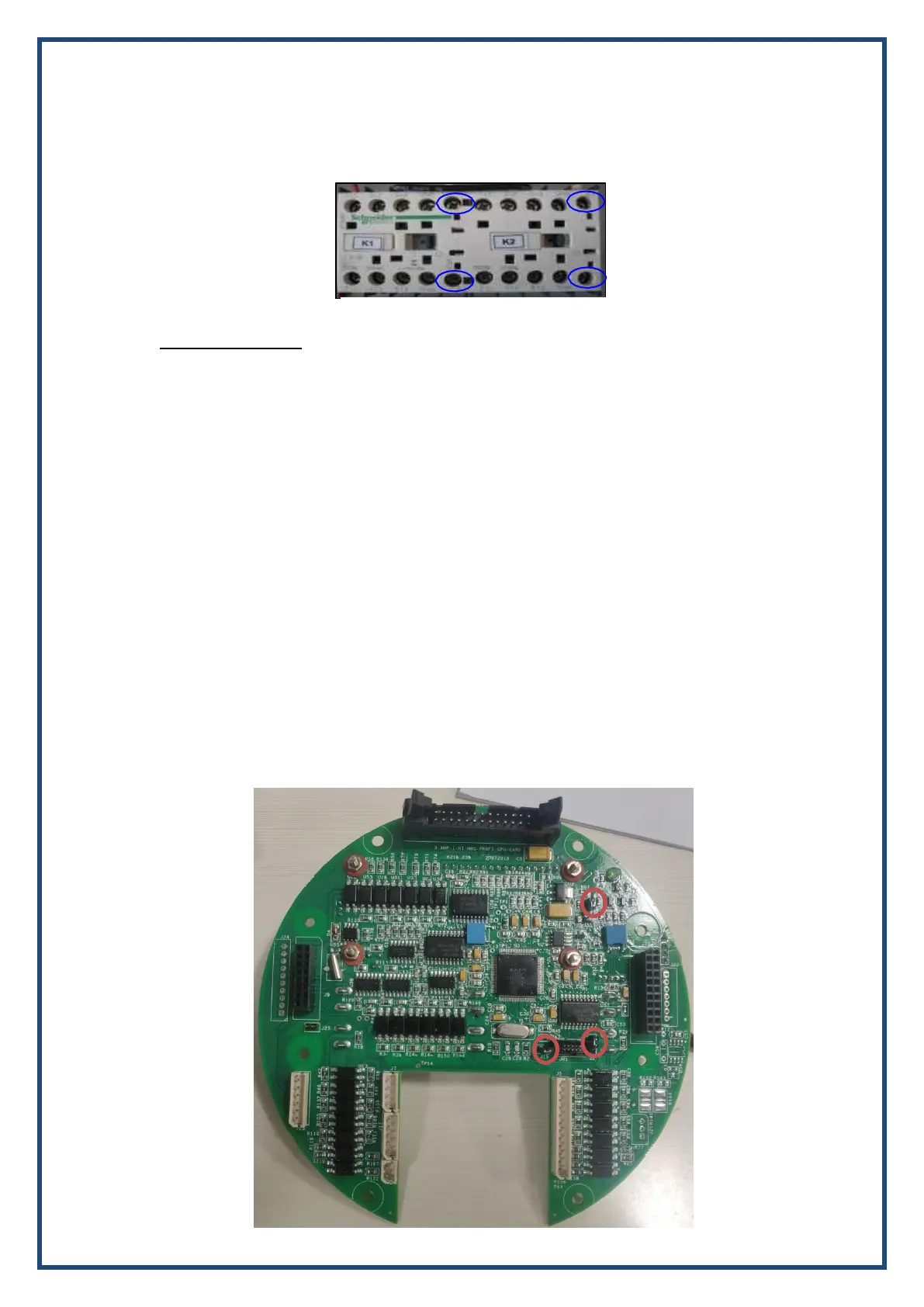
XVI. LCD Display is blank with back light ON:
Check whether all respective connectors are plugged properly and ensure that the shorting
link is connected properly on J2, J3 & J19 of CPU card as shown below.