This document is an installation manual for AUTEC 4-column electro-hydraulic vehicle lifts, covering models AL3044, AL4044, AL4044/VS, AL4044/VANS, AL5044, and AL5044/T. It provides detailed instructions for assembly, safety, and connection, issued on 22-7-2008.
Function Description
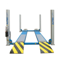
The AUTEC 4-column vehicle lift is an electro-hydraulic system designed for lifting vehicles in industrial settings, service, maintenance, and repair activities. It consists of two platforms and four posts, with the columns fixed to the floor using bolts. The lifting mechanism utilizes a hydraulic cylinder that converts horizontal movement via cables and pulleys into vertical movement, enabling the platforms to raise and lower vehicles. The lift is controlled by a control box typically mounted on one of the control posts.
The manual emphasizes that installation must be performed by authorized personnel who possess specific experience in industrial work, service, maintenance, and repair activities. These individuals must also be capable of interpreting the drawings and descriptions provided in the manual and be aware of all applicable general and specific safety regulations in the country of installation.
Important Technical Specifications
Lift Models Covered: AL3044, AL4044, AL4044/VS, AL4044/VANS, AL5044, AL5044/T.
Installation Site Requirements:
- Minimum Height from Floor: 5000 mm. This ensures adequate vertical clearance for the lift's operation and any vehicles being serviced.
- Minimum Distance from Walls: 1 m. This provides sufficient space around the lift for safe operation and access.
- Minimum Working Area: 500 mm. This ensures adequate room for personnel to work around the lift.
- Power Supply: The installation site must have a power supply point that meets all applicable legal requirements. For 400 V systems, wires must be at least 2.5 mm² with a maximum 16A fuse. For 230V 3-phase systems, wire size must be at least 4 mm². The supply cable must include an earthing wire and be suitable for a firm and final connection.
- Environment: The lift must be installed in an enclosed space, protected from weather influences. It should be located at a sufficient distance from storage areas of paint and wax, and rooms where there is a danger of explosion.
Control Box Components (Fig. 3):
- Mainswitch (11): Controls the overall power to the lift.
- Lifting Motion Button (12): Initiates the upward movement of the lift.
- Descend Button (13): Initiates the downward movement of the lift.
- Locking (14): Likely refers to a mechanism or indicator related to the lift's safety locking system.
Electrical System (Fig. 23, 24):
- Fuses: F1 = 2 Amp. Fuse.
- Switches: S1/S2 = Lift/descend button, S3 = Locking button, FC1-2-3-4 = Microswitches, FC5 = Microswitch.
- Contactors: KM = Contact.
- Valves: Y1 = Hydraulic solenoid valve, Y2 = Pneumatic solenoid valve.
- Relays: Temp = Time relay for unlocking.
- Motor (M1): 230/400 V, 50 Hz.
- Transformer (Tr): 400/24 VA, 50 Hz.
Cable Connections (Fig. 24):
- Cable A: Connects to terminals 12 and 15.
- Cable B: Connects to terminals 16, 21, 6, 13, 18, 14, 17, and 22.
- Cable C: Connects to terminals 12 and 10.
- Cable D: Connects to U, V, W, 0, and thermal relays.
- Cable E: Connects to terminals 1, 5, 6, and 10.
Usage Features
Operation:
- The lift is controlled via a control box with distinct buttons for lifting and descending.
- A main switch provides overall power control.
- Safety locking mechanisms are integrated into the system, engaged by a dedicated locking button.
Installation Process:
- Unpacking and Placement: Open packaging, place columns on the installation location, and fit locking strips. Ensure the strip runs behind the central strip in the column.
- Crossbeam Installation: Place crossbeams on dollies. The crossbeam with the fuse box must be on the same side as the operating column.
- Cable and Hose Routing: Lead steel cables and electricity cables through the crossbeams. Connect air hoses to locking cylinders and the compressed air supply.
- Guidance Blocks: Fit runners and guidance blocks in the crossbeams. Ensure spring rings are fitted to secure blocking plates.
- Column Alignment: Place columns by sliding them against the crossbeams. Secure lifting cables in the column.
- Control Unit Installation: Fit the control unit to the column and connect cabling as per the electrical diagram.
- Hydraulic System: Remove the hydraulic hose from under the platform and route it with the pneumatic hose, electrical cables, and return pipe to the control column. Fill the oil reservoir.
- Safety Components: Fit the safety switch at the bottom of the column. Suspend safety bars and fit catch bars with double nuts at the top of the columns.
- Adjustments: Adjust column cables to ensure they are taut when driving plates are on the floor. Adjust safety switches (cable breach/weakness) to approximately 1.5/2 mm. Adjust the final switch at the bottom of the column.
Safety Features:
- Safety Zone: During installation, no unauthorized persons are allowed in the safety zone around the lift.
- Safety Checks: After installation, a responsible engineer must check all safety arrangements to ensure proper functioning.
- Emergency Cable: If a permanent power supply is not immediately available, an emergency cable can be used for testing, but the final wiring must be laid by a qualified technician.
Maintenance Features
Pre-Installation Checks:
- Damage Inspection: Check for any damage during transportation upon opening crates.
- Component Verification: Verify that all components listed in the Packing List are physically present.
Storage:
- The packed lift must be stored in a covered area at temperatures between -10 °C and +40 °C.
- It must not be exposed to direct sunlight.
Cleaning:
- After installation, the responsible engineer must ensure the lift is delivered to the client in a "squeaky clean" condition.
Documentation:
- Goods Receipt Report: After installation, the installation engineer must prepare a detailed goods receipt report, noting any complaints or observations from the client. This report must be signed by both the engineer and the client and submitted to the technical department.
Electrical System Maintenance:
- The manual provides a detailed electrical diagram (Fig. 23) and connection numbers (Fig. 24) to assist with troubleshooting and maintenance of the electrical system. This includes information on fuses, switches, contactors, valves, and motor connections.
The manual emphasizes the importance of following all instructions carefully to ensure safe and correct installation and operation, thereby preventing injury to persons or damage to equipment.