INSTALLATION-MANUAL
4-Colomn
AL3044
AL4044
AL4044/VS
AL4044/VANS
AL5044
AL5044/T
ISSUED 22-7-2008
AUTEC Hefbruggen bv
Fig.3
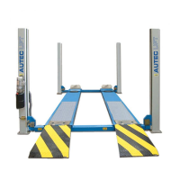
5. INSTALLATION
Installation may only be done
by persons authorised to do so.
BEFORE STARTING INSTALLATION,
PLEASE RECHECK ALL
THE
CONTROL POINTS.
The lift must be installed in an enclosed
space where weather
influences do not
have any effect. The place of installation
must be at a sufficient distance from the
storage locations of paint and wax, and
also rooms where there is a danger of
explosion.
ELECTRICAL POWER SUPPLY
POINT.
The client must ensure that there is a
power
supply point near the installation
site, which satisfies all the applicable
legal requirements (see page 4). If such
power supply is not available, the
installation technician will arrange for
an emergency cable. The lift shall be
tested after the emergency power
supply has been dismantled. The client
must then arrange for a duly qualified
and recognised installation technician to
lay the final wiring.
IMPORTANT INSTALLATION
MEASURES
The lift must be installed taking into
account
the dimensions of other objects
(Fig. 4), and the rules and regulations
applicable in the country where the lift is
installed.
In particular, attention should be paid to
the following :
The
minimum height from the floor,
at the installation location, must be
5000 mm
The minimum distance from the
walls must be 1 m.
The minimum working area is 500
mm
Adequate room for working
Adequate room for
maintenance,
access-/ and exit routes.
Position with respect to other
machines
In the neighbourhood of
the power
supply point to ensure problem-free
connection.
Fig.4
During the installation no
unauthorized persons may be
present in the safety zone around the
lift.
• Remove
the packaging from the
driving plates.
Place the driving tracks on dollies and
convey
them to the general location of
installation. The driving track with the
cabling / hydraulics under the driving
plate must be installed on the same side
as the operating column (fig. 5)
Fig.5
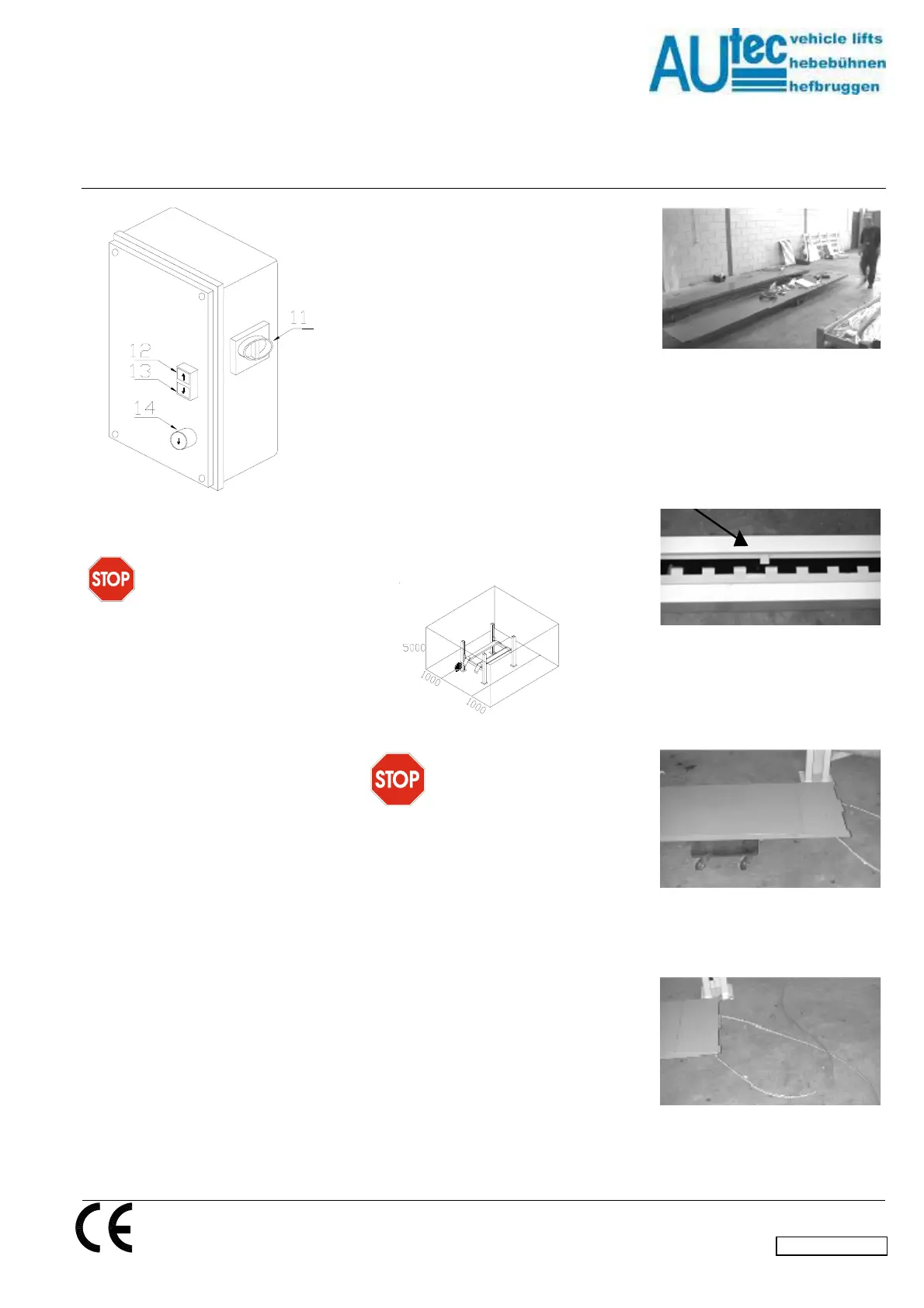
Open the packaging of the columns and
place
the columns on the installation
location. Fit the locking strips in the
columns. Take care: that this strip runs
behind the strip (1) in the centre of the
column (Fig.6).
Fig.6
Place the crossbeams on dollies. Take
care:
that the crossbeam with the fuse
box is placed on the same side as the
operating column (Fig.7).
Fig.7
Remove the steel cable from under the
driving plate (Fig.8).
Fig.8
Lead the cables to the non-operating
side through the crossbeam. The cable
Industrieterrein IJsselveld, Vlasakker 11, 3417 XT MONTFOORT, The Netherlands
Tel:+31 348 477000 Fax:+31 348 475104 E-mail: info@autec.nl
en/TD-AL4044-03
 Loading...