INSTALLATION-MANUAL
4-Colomn
AL3044
AL4044
AL4044/VS
AL4044/VANS
AL5044
AL5044/T
ISSUED 22-7-2008
AUTEC Hefbruggen bv
Fit the safety switch at the bottom of the
column and connect it.
Remove the hydraulic hose from under
the platform and lead
this together with
the pneumatic hose, the electrical cable
of the control unit, the return pipe and
any electrical cable for the lighting
through the flexible hose to the control
column (Fig.17).
Industrieterrein IJsselveld, Vlasakker 11, 3417 XT MONTFOORT, The Netherlands
Tel:+31 348 477000 Fax:+31 348 475104 E-mail: info@autec.nl
Fig.17
Fill the oil reservoir.
Connect the electrical power to the
control unit
Align the columns, using if necessary
spacers secured with M12x100.
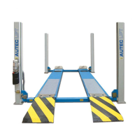
Suspend the safety bars in the column.
Fit
the catch bars at the tops of the
columns with double nuts. 1 nut must be
located under the top plate. Caution:
the catch bar must be suspended loose
in the column (Fig. 18+19)
Fig.18
Fig.19
1. Adjust
the column cables. Ensure
that the cables are taut when the
driving plates are on the floor.
2. Adjust the safety
switches (cable
breach/weakness) to
approximately 1.5/ 2 mm (Fig.20)
Fig.20
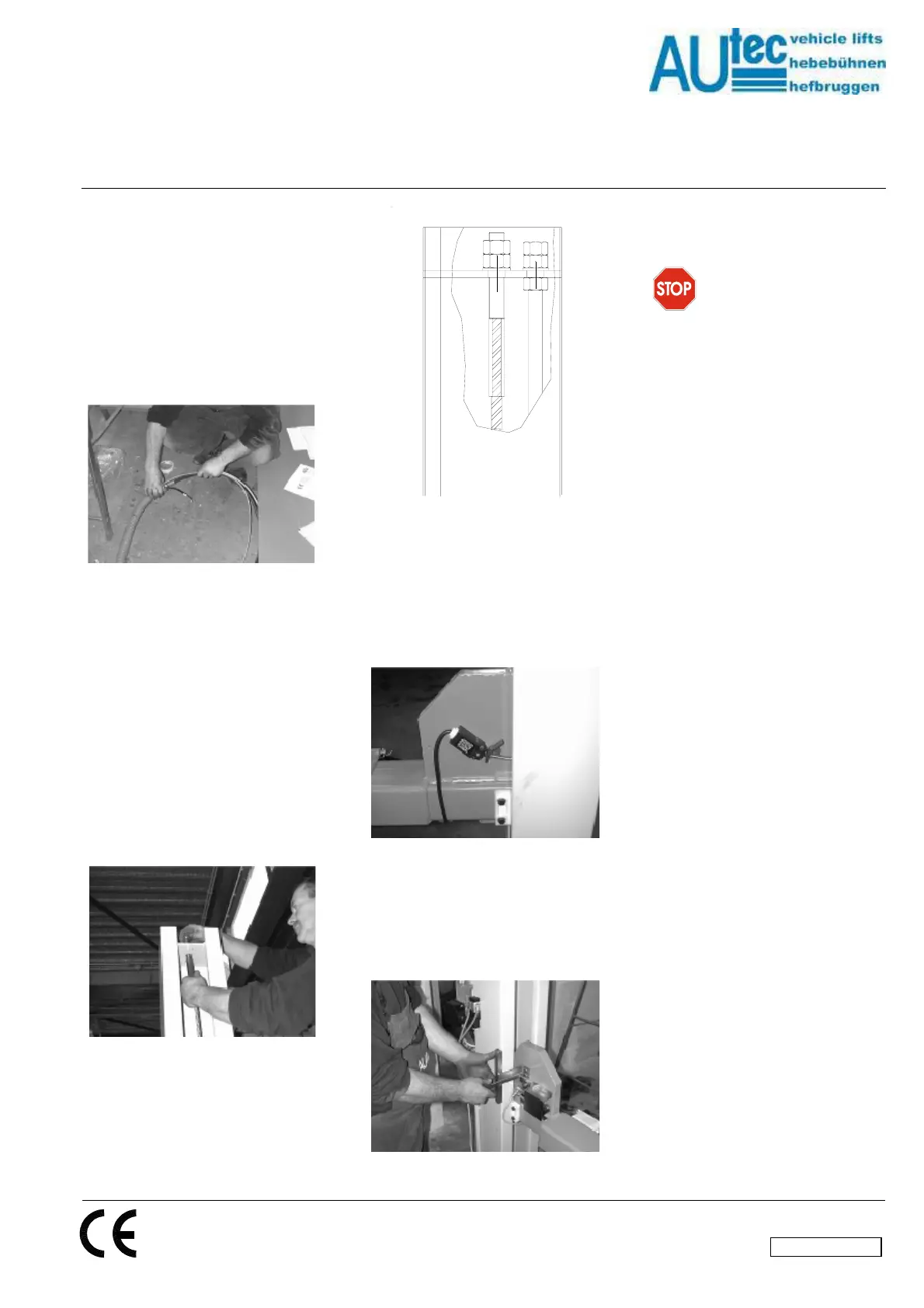
Fit the pin that is to serve the switch at
the bottom of the column.
Then adjust
the final switch at the bottom of the
column (Fig.21).
Fig.21
6. CONNECTING TO THE
MAINS
WARNING
The following actions must only be
carried
out by duly authorised
personnel :
First check the following points before
connecting to the mains:
-
-
-
The electrical system at the
workplace must be protected
according to the applicable
standards.
The wires must be of the following
sizes : in the case of 400 V
they
must be at least 2.5 mm
2
fuse max
16A. In the case of 230V 3-phase
supply, the wire size must be at
least 4 mm
2.
- The supply cable must be provided
with an earthing wire, and must be
suitable for a firm and final
connection.
Connect the power supply cable to
the control cabinet according to
Fig. 23.
Put the main switch in the “1” position.
Check
the direction of rotation of the
motor by pressing the lifting-motion
button.
7. SAFETY CHECKS
After the complete installation of the lift,
the responsible installation engineer
must check all the safety arrangements
on the lift to check whether they are
working properly.
CLEANING OF THE LIFT (Fig. 17)
The installation engineer responsible
must
take care to see that the lift which
is installed is delivered to the client in a
'squeaky clean' condition.
en/TD-AL4044-05
 Loading...