Do you have a question about the Auto Meter 4366 and is the answer not in the manual?
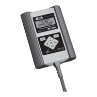
Diagram showing gauge connections for light wires, ground, and power.
Lists wire assignments for the temperature module's terminal block for thermocouples and power.
Describes Manual and Automatic display modes and how to toggle between them.
Instructions for selecting display channels using the Channel Select button in Manual Mode.
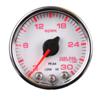
How to view, save, and clear peak values for both pyrometer channels.
Guide to setting alarm thresholds for both pyrometer channels using the Set/Store button.
This document describes the installation and operation of the Auto Meter 2 Channel Pyrometer, designed for measuring Exhaust Gas Temperatures (EGTs) or Cylinder Head Temperatures. It covers models 4366, 4368, 4466, 4468, 5466, 5468, and 5766.
The 2 Channel Pyrometer is an electronic device that continuously monitors and displays temperature readings from two independent channels. It is capable of tracking peak temperatures and alarm conditions for both channels, even when the unit is powered off and back on. The device is designed for use in automotive applications, likely for performance monitoring.
The pyrometer offers several user-configurable features accessible through its display and buttons:
The pyrometer has two main display modes:
The "Auto Mode" / "Man. Mode" button toggles between these two modes.
To select a specific channel for display (only available in Manual Mode), press the "Channel Select/Peak Recall" button.
The manual provides several tips to ensure proper operation and longevity of the pyrometer:
| Brand | Auto Meter |
|---|---|
| Model | 4366 |
| Category | Measuring Instruments |
| Language | English |