Disable ignition as indicated in the Starter-Draw Test on page 10.
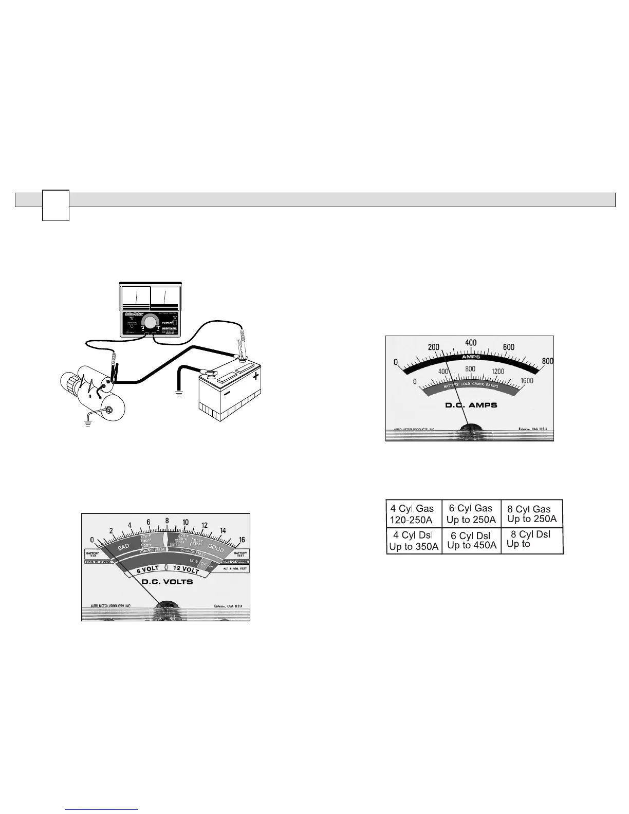
1. Connect the tester as shown below. A with the RED clamp to battery
pos itive and the BLACK clamp to the terminal on the starter, which is
con nected to the solenoid directly or by cable.
2. Observe the voltage reading while cranking the engine.
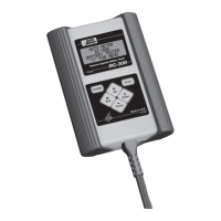
3. On most vehicles, the reading should not exceed 0.5 volts (see
example below).
4. If the voltage drop exceeds 0.5 volts, check the voltage drop through
each cable, across each connection including the solenoid.
5. Repair and/or replace as necessary.
STARTER CIRCUIT TEST
STARTER DRAW TEST CONT.
Example:
1. With ignition disabled crank vehicle and observe lowest volt reading.
For this example, we’ll say it reads 11 volts.
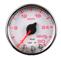
2. Apply a load with the Load knob until voltmeter reads 11 volts (see
example page 10). Quickly read the ammeter. In this case it reads
240 amps. Remove the load (knob turned fully counterclockwise).
3. We now know the starter draw is 240 amps and that it is generally
within specications for a V8 gasoline engine (see Maximum Amps
chart on page 11).
Maximum Amps
If manufacturer’s specications are not available, the chart below can be
used as a general guideline for light duty engines and starters. Amounts
are in Amps.
5
14
11