Do you have a question about the Auto Page RF-425LCD and is the answer not in the manual?
Details the connections and functions of the main 5-pin wire harness for system power and outputs.
Explains the 10-pin mini connector wiring for various system inputs, triggers, and outputs.
Provides wiring details for the 6-pin door lock connector for negative and positive systems.
Details the 4-pin orange connector for the 2-stage shock sensor and trigger inputs.
Covers RF antenna placement and the 4-pin black connector for the AM transmitting module.
Wiring diagram for adding actuators using a 5-wire reverse polarity configuration.
Illustrates how to wire and add actuators for front and back doors.
Procedure to program transmitters to the alarm system, including entry and exit steps.
Configuration options for alarm features A, such as siren confirmation and automatic rearm.
Configuration options for alarm features B, including door lock pulses and arming modes.
Configuration options for alarm features C, covering channel outputs and timer controls.
Detailed steps for programming timer control outputs for channels 2, 3, and 4.
| Type | Car Alarm |
|---|---|
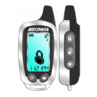
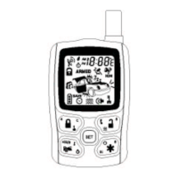
| Remote Type | LCD |
| System Type | 2-Way |
| Number of Buttons on Remote | 5 |
| Operating Voltage | 12V DC |
| Alarm Output | Yes |
| Immobilizer Output | Yes |
| Features | Keyless Entry, Remote Start |