4100ES Network Display Units with SPS Power Supplies for 4120 Network
Page 2 AC4100-0036 Rev. 19 3/2018
4120 Network Overview
When connected to other 4120 network nodes, individual fire alarm
control panels become components of a distributed intelligence system.
Each panel that directly connects to the 4120 network is called a
network “node” and is capable of performing individual supervision and
control on its locally connected devices but has the ability to inform
the 4100ES NDU (as well as other network control panels) of point
status and panel condition. This allows system information to reach
the proper location for appropriate system response. Multiple 4100ES
NDUs (separately packaged) can be connected to a 4120 network to
duplicate common information at separate locations, or direct selected
information by type such as troubles, alarms, control, etc.
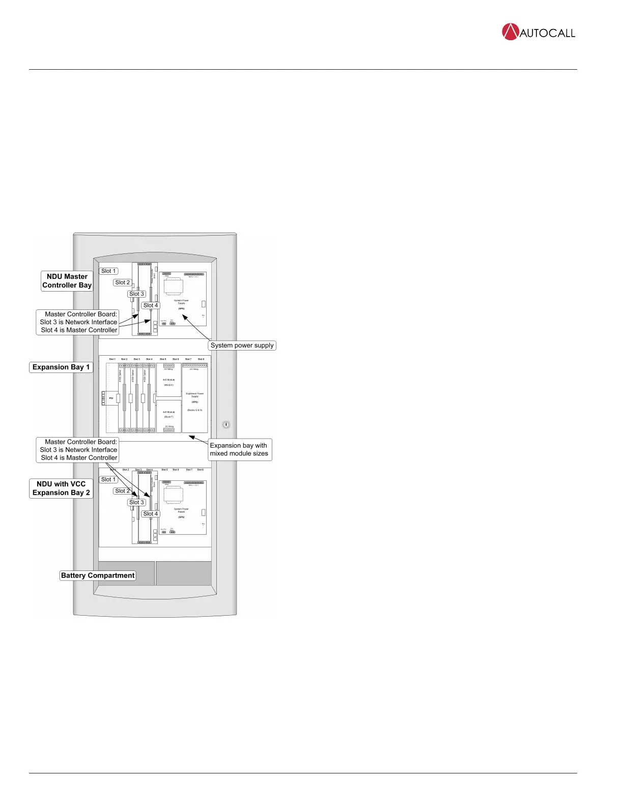
NDU with VCC Internal Module Bay Reference
Figure 2: NDU with VCC Internal Module Bay Reference
(exact layout is determined by specific system requirements)
NDU Module Bay Description
The NDU Master Controller Bay (top) includes a special purpose
system power supply with battery charger (SPS), the master controller
board, a 4120 modular network interface card, and operator interface
equipment similar to that used on the standard fire alarm control
modules. Slots 1 and 2 are available for single slot panel mounted
modules.
The NDU with VCC includes an expansion bay with separate master
controller board, 4120 modular network interface card, and a standard
SPS. This results in two separate network nodes residing within the same
cabinet.
In this bay (typically the second expansion bay), Slots 1 and 2 are
available for single slot panel mounted modules and optional LED/switch
modules can also be mounted.
The Battery Compartment (bottom) accepts two batteries, up to 50
Ah, to be mounted within the cabinet without interfering with module
space.
Refer to NDU with VCC Internal Module Bay Reference for typical three
bay cabinet module location.
Standard Module Details
NDU (top bay) master controller & motherboard includes a
master controller, master controller motherboard, 4120 Modular
NIC, and SPS power supply
• The master controller mounts in slot 4 of a two slot motherboard
(slots 3 and 4 of the master controller bay) and provides one RUI+
communications channel (Class B or Class A), available at slot 4. A 4120
modular network interface card is mounted in slot 3.
• The NDU bay RUI+ communications output (configurable for isolated
or un-isolated operation) supports up to 31 devices per master
controller at up to 2500 ft (762 m) for single run, or 10,000 ft (3048 m)
total if wiring is Class B and T-tapped. If more distance is required, up
to four total RUI channels are supported per master controller (up to
three A100-1291 RUI expansion modules may be added). A100-1291
provides un-isolated RUI communications.
• System power supply (SPS) is rated for 9 A total; includes battery
charger, one 2 A aux power output selectable for detector reset, door
holder, or coded output operation and expansion slot for one city
circuit (A100-6031 or A100-6032) or alarm/supv/tbl relay (A100-6033)
option. See data sheet AC4100-0031 for details.
• Outputs are power-limited, except for the battery charger
Note: SPS IDNet channel, NACs and aux relay are disabled in NDU bay.
VCC (expansion bay) includes a master controller, master
controller motherboard, 4120 Modular NIC and SPS power supply
with IDNet communication channel
• The master controller mounts in slot 4 of a two slot motherboard
(slots 3 and 4 of the master controller bay) and provides one RUI+
communications channel (Class B or Class A), available at slot 4. A 4120
modular network interface card is mounted in Slot 3.
• The VCC bay RUI+ communications output (configurable for isolated or
un-isolated operation) supports up to 31 devices per master controller
at up to 2500 ft (762 m) for single run, or 10,000 ft (3048 m) total
if wiring is Class B and T-tapped. If more distance is required, up to
four total RUI channels are supported per master controller (up to
three A100-1291 RUI expansion modules may be added). A100-1291
provides un-isolated RUI communications.
• System power supply (SPS) is rated for 9 A total; includes battery
charger, auxiliary power, auxiliary relay, three on-board NACs, and
provisions for either an optional city connect module or an optional
alarm relay module (see data sheet AC4100-0031 for details)
• Battery charger is dual rate, temperature compensated, and charges
up to 50 Ah sealed lead-acid batteries mounted in the battery
compartment (33 Ah for single bay cabinets); also is UL listed for
charging up to 110 Ah batteries mounted in an external cabinet (see
data sheet AC2081-0012 for details) includes battery charger status
and low or depleted battery conditions; status information provided to
the master controller for battery voltage, charger voltage and current,
actual system voltage and current, and individual NAC currents
• Battery and charger monitoring includes battery charger status and
low or depleted battery conditions; status information provided to the
 Loading...