Revised 8/14/02 • U141v+ 4 © 2002 Automated Logic Corporation
Start-Up Checklist
1. Use the appropriate version of Eikon for
WebCTRL or Eikon 3.0a or later to create
GFBs for U-Line modules. Be sure to
enable the Zone GFB option in Eikon for
WebCTRL or Eikon. Refer to “Writing GFBs
for the U141v+” on page 9 for more
information.
2. Use the appropriate module driver. (See
“Job Start-Up” on page 3.)
3. Connect the U-Line modules to the Unet
and the UNI.
4. Transfer the U-Line modules’ GFBs to the
UNI.
Mounting
It may be necessary to re-position the motor
assembly to mount the U141v+ properly.
• Remove the U141v+’s cover.
CAUTION
The circuit board is not
attached to the card housing. Take care
when removing the cover.
• Use a Phillips #2 or Torx 20 screwdriver
to detach the motor assembly from the
card. Re-position the assembly, taking
care to re-route the cable attaching the
assembly to the circuit board. Re-attach
the assembly and replace the module’s
cover.
1. Place the module on the VAV box by
feeding the damper shaft through the
shaft slot (see Figure 2).
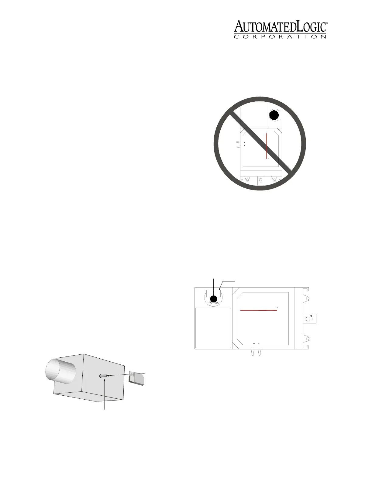
CAUTION
Do not position the module
so that the shaft slot is in the upper right
of the module (see Figure 3). This position
may cause condensation from the VAV
shaft to drip on to the electronic
components of the U141v+.
2. Position the damper shaft and motor in
the desired position, then tighten the shaft
clamp (see Figure 4).
3. Insert a mounting screw into the
stabilizing slot and tighten it to secure the
module (see Figure 4).
Addressing
The U141v+ has dual rotary switches for
assigning the board address. The top switch
corresponds to the tens digit and the bottom
switch corresponds to the ones digit (see
Figure 2. U141v+ Placement on VAV Box
Damper Shaft
Feed the damper
shaft through
the module's shaft slot
VAV BOX
Figure 3. Improper Mounting Position
Figure 4. Mounting Slots
MS/TP
BACnet
TM
UTOM ATED
CO RPO RATION
A
OGIC
L
HiL
o
Flow
R
Shaft Slot
Shaft Clamp
Stabilizing Slot
MS/TP
BACnet
TM
UTOM ATED
CORPO RATION
A
OGIC
L
HiLo Flo w
R