Revised 8/14/02 • U141v+ 7 © 2002 Automated Logic Corporation
To communicate through the LogiStat port,
the U141v+ must:
• be connected to a UNI on an ARC156
network segment
• use the appropriate module driver
For SuperVision systems, use a version
6.01d or later of the U1M, U3M, U5M, or
UNM module driver
Communication speed is fixed at 1200 baud.
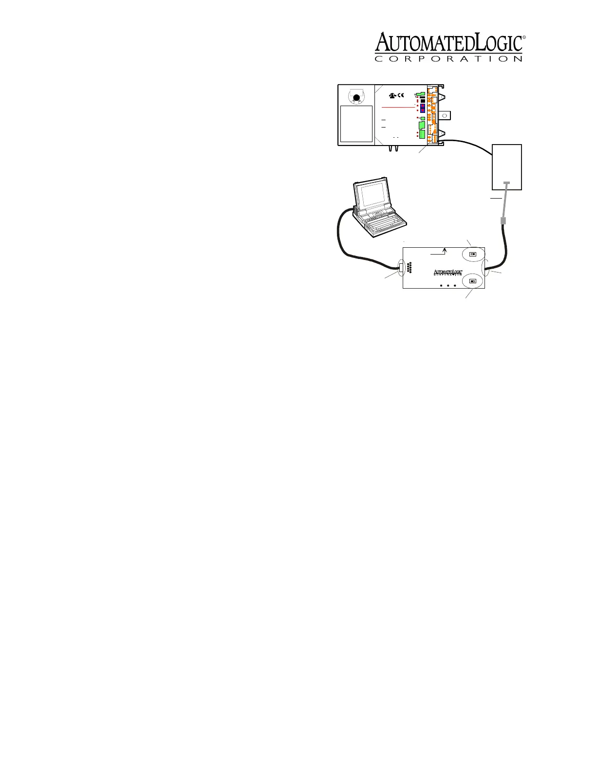
1. Connect the computer’s serial port to the
EIA-232 port of the APT using a standard
straight-through cable.
2. Set the APT’s Mode Select switch to TTL
(see Figure 9 on page 7).
If you are using a LogiStat Plus without
supplemental power to the APT, make
sure the LED on the Logistat Plus is on
indicating that it can provide power to the
APT. If the LED is not on, you can provide
power to the APT using the Supplemental
Power +5V dc connection (see Figure 9 on
page 7) and the special power cable to a
laptop keyboard jack, or an external
supply, such as a 5V dc transformer.
3. Define the connection type.
In SuperVision v3.0, define the connection
as Access Port.
In SuperVision v2.6, define the connection
as Direct Connect.
4. Set the baud rate at 1200 bps.
5. Attach the LogiStat Adaptor cable (ALC
part number 235022) to the APT cable.
Use this assembly to connect the APT’s
Access Port to the LogiStat’s LogiPort.
While connected, the LogiStat Pro
displays “LP” indicating that the LogiStat
Pro will not respond to input from the
keypad.
NOTE
When the LogiStat Adaptor cable
is inserted into the LogiPort, the U141v+
can no longer read the LogiStat inputs.
The U141v+ continues to use the last valid
temperature and setpoint adjust readings
obtained before the cable was inserted
into the LogiPort. If the occupancy
override timer was active when the
connection was made, it continues to
count down, but no new values can be
obtained for these inputs until the
LogiStat Adaptor cable is removed. See
the
Eikon for WebCTRL Microblock
Reference Guide
or the
Eikon Microblock
Reference Guide
for more information
about the LogiStat microblock.
6. Disconnect the LogiStat Adaptor cable
from the LogiStat’s LogiPort when
finished to allow the U141v+ to read
inputs from the LogiStat.
Input Wiring
The U141v+ inputs support the types of
signals listed below. The LogiStat, LogiStat
Plus, and LogiStat Pro sensors are supported
through the module’s LogiStat port. Refer to
Figure 9. Using the LogiPort
EIA-232
Port
9
Rx
6
1
2- Tx out
3- Rx in
5- Gnd
1,6,8- +10V or floating
Tx +5V
APT
5
Exec. 4 relay
Isolate Network
Mode Select
TTL
485
ACCESS
PORT
Mode Select
Switch
Exec. 4 Relay
Switch
Access
Port
LogiStat Adaptor Cable
LogiStat
LogiStat
Port
24 V ac
Gnd
24 Vac
Gn
d
On Off
O
n
e
s
T
e
n
s
Power
Rx
DO-
1
Gn
d
+10
V
Gn
d
AO-
1
Gnd
IN-
2
Gnd
IN-
1
CCW
CW
Motor
Dir
.
24Vac
50-60Hz
7VA
0.29A
Use Copper
Conductors
Only
Class2
ManagementEquipment
TYPE:00 3410
E14390
0
88FO
R
Enc lo s ed En er g y
24V Max,1A Max
Output
Tx
Run
MS/TP
BACnet
TM
UTOMATED
COR PO R ATIO N
A
OGIC
L
H
i
Lo Flow
1
2
Error
Input:5V Max
AO:0-10Vdc
5mA
Max
LS5v
S
w
Tem
p
Gnd
L
o
g
i
S
t
a
t
Interc onnect theOutputsof
DifferentClass2 Circuits.
To ReduceTheRiskofFire
orElectric Shock,Do Not
CAU T I ON :
tobe mountedinside
ifmountedoutside.
Warranty voided
thebuilding envelope.
Thisproductwas designed
CAUTION:
R
U1 41v+
Supplemental
Power
+5V dc