Revised 11/26/01 • UNI/32 3 © 2001 Automated Logic Corporation
Real Time Clock
A battery-backed real
time clock that keeps track of time in the
event of a power failure.
Protection
Voltage, current, and ESD
protection on incoming power and
CMnet.
Bat tery
Lithium 3V Primary Battery, Type
BR2330 (not replaceable). Provides a
minimum of 10,000 hours of data
retention during power outages.
Listed by
UL 916 (PAZX), cUL C22.2 No.
205-M1983 (PAZX7), FCC Part 15 -
Subpart B - Class A.
Mounting
Screw the UNI/32 into an enclosed panel
using the mounting holes provided on the
cover plate. Be sure to leave about 2 inches (5
centimeters) on each side for wiring.
Power Wiring
CAUTION
The UNI/32 module is a Class 2
device (less than 30VAC, 100VA maximum).
Take appropriate isolation measures when
mounting the UNI/32 module in a control
panel where non-Class 2 devices (for
example, 120VAC) or wiring are present.
You can power several modules from the
same transformer if you maintain the same
polarity.
The UNI/32 has an operating range of
21.6VAC to 26.4VAC. If voltage measured at
the module’s power input terminals is outside
this range, the module may not work
properly.
1. Turn the module’s power off. This
prevents the module from being powered
up before the proper voltage is verified.
2. Make sure the 24VAC power source is off.
3. Connect the power wires to the module’s
power terminals labeled Ground and
24VAC.
4. Apply power to the transformer.
5. Make sure that 24VAC is present at the
module’s power input terminals.
6. Set the module’s address. Refer to
“Addressing” on page 5 for details about
setting the address.
7. Turn the module’s power switch on.
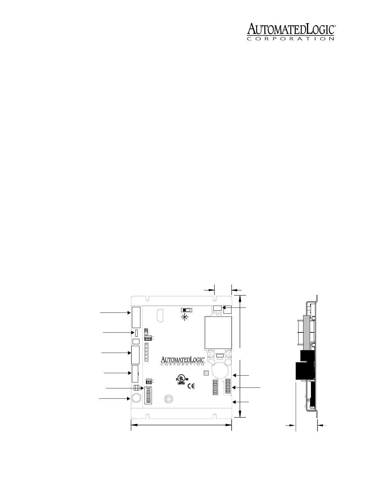
Figure 2. Module Dimensions and Layout
TYPE : COM32
E143900
Open E nergy
Management Equipment
88FO
R
Net +
Net -
Optional shield
38.4K
On
1
2
4
8
16
32
64
9600CMnet baud
Diag transmit
Diag receive
Unettransmit
Unet receive
CMnet transmit
CMnet receive
Error
Run
9600/38.4k
ARC156
port
Access
connection
CMnet
(Module)
Address
CMnet
button
Format
CMnet Mode
Unet 1 Connection
OptionalShield
-
+
-
+
EIA-4 85
N/C
N/C
N/C
UNI
24 Vac
Ground
Only
Conductors
Use Copper
0.3A
7.2VA
50-60 Hz
24 Vac
Class 2
UseSingleClass2Only
Off On
Connector
Power
Indicator
Power
Switch
Power
Port
Diag
gnd
dtr
tx
rx
dcd
5
4
3
2
1
9
8
7
6
n/c
n/c
+10v
n/c
EIA-232
Unet 2 Connection
Auxiliary
device
port
Over ARCNET156 KB aud
BACNet
61/4"
15.9 cm
11/8"
2.9 cm
71/8"
18.1 cm
15/8"
4.1 cm
Power Switch
Format Button
Addressing
DIP Switches
Diag Port
Keypad Display Port
LED Indicators
Access Port
UNI /3 2
2M
Unet Connection Port
Configuration Jumpers
Unet Connection Port
Connection
Port
CMnet
 Loading...