p. 26/46
TLxx-MT-EN-04
7.2.5. Shock abSorber
The cam fixed at the end of the shock absorber makes pressure on one of the rollers, which slows down the
movement at the end of the cycle and dampens the shock against the lock at the point of impact.
The rotation cycle is quieter and the kinematic parts undergo less mechanical stress.
Fig. 20 Shock absorber option
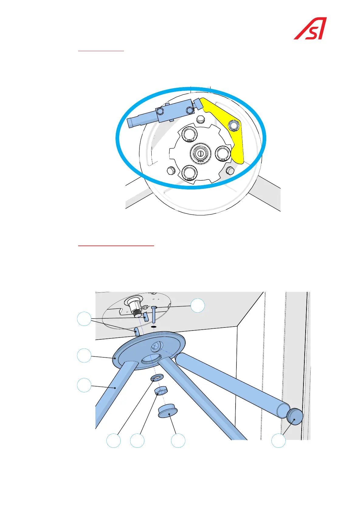
7.2.6. fixed arm turret aSSembly
The fixed arm turret [5.1] is held in place on the main axle by a spacer, two wedges [5.5] and a locking nut [5.3].
The stainless steel fixed arms [5.4] are fitted with a steel sleeve at one end and a black plug [5.7] at the other end.
Three screws M8 x 45 [5.8] secure the arms; the sleeves have a threaded hole and the aluminium turret has a hole
passing through it for inserting the screw.
5.1
5.8
5.4
5.2 5.3 5.6 5.7
5.5
Fig. 21 Fixed arm turret