DL06 Micro PLC User Manual; 3rd Edition Rev. E
4–18
Chapter 4: System Design and Configuration
1
2
3
4
5
6
7
8
9
10
11
12
13
14
A
B
C
D
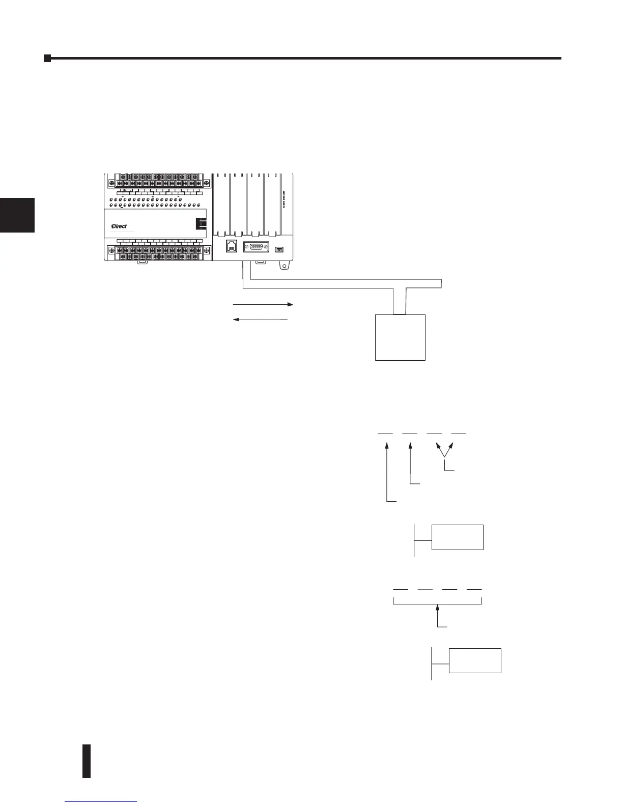
When using the DL06 PLC as the master station, simple RLL instructions are used to initiate
the requests. The WX instruction initiates network write operations, and the RX instruction
initiates network read operations. Before executing either the WX or RX commands, we will
need to load data related to the read or write operation onto the CPU’s accumulator stack.
When the WX or RX instruction executes, it uses the information on the stack combined with
data in the instruction box to completely define the task, which goes to the port.
The following step-by-step procedure will provide you the information necessary to set up your
ladder program to receive data from a network slave.
Slave
Master
WX
(write)
RX (read)
Network
LOGI
C
Koyo
0
6
C0 C4C2X1 X3 X4 X6 X11X13 X14X16 X21X23 N.C.
C1 C3X2 X5 X7 X10X12 X15 X17X20 X22X0
N.C.
AC
(
N
)
24V
0V
N.C.
C1 C3Y0 Y15Y12Y10Y17Y7Y5Y2
C0 C2 Y16Y14Y13Y11Y6Y4Y3Y1
LG
G
AC
(
L
)
D0-06DR
2.0AOUTPUT: 6-240V 50 - 60Hz 2.0A, 6 - 27V
INPUT: 12 - 24V3 - 15mA
Y
X
40VA50-60HzPWR: 100-240V
01 2345 6710 11 12 13 14 15 16 17 20 21 22
23
PORT1 PORT2
TERM
RUN STOP
PWR
RUN
CPU
TX1
RX1
TX2
RX2
Internal port (hex)
Port number (BCD)
Slave address (BCD)
LD
KF201
6 4
(BCD)
# of bytes to transfer
LD
K64
Step 2: Load Number of Bytes to Transfer
The second Load (LD) instruction determines the
number of bytes which will be transferred between
the master and slave in the subsequent WX or RX
instruction. The value to be loaded is in BCD
format (decimal), from 1 to 128 bytes.
Step 1: Identify Master Port # and Slave #
The first Load (LD) instruction identifies the
communications port number on the network
master (DL06) and the address of the slave station.
This instruction can address up to 99 MODBUS
slaves, or 90 DirectNET slaves. The format of the
word is shown to the right. The “F2” in the upper
byte indicates the use of the right port of the DL06
PLC, port number 2. The lower byte contains the
slave address number in BCD (01 to 99).