DL06 Micro PLC User Manual; 3rd Edition Rev. E
4–17
Chapter 4: System Design and Configuration
1
2
3
4
5
6
7
8
9
10
11
12
13
14
A
B
C
D
Example 3: T10 Current Value 484 Mode
Find the MODBUS address to obtain the PLC Address (Dec.) + Mode Address
current value from Timer T10. TA10 = 8 decimal
1. Find Timer Current Values in the table. 8 + 3001
=
2. Convert T10 into decimal (8).
3. Add the MODBUS starting address for the mode (3001).
Example 4: C54 584/984 Mode
Find the MODBUS address for Control Relay C54. PLC Addr. (Dec.) + Start Address + Mode
1. Find Control Relays in the table. C54 = 44 decimal
2. Convert C54 into decimal (44). 44 + 3072 + 1
=
3. Add the starting address for the range (3072).
4. Add the MODBUS address for the mode (1).
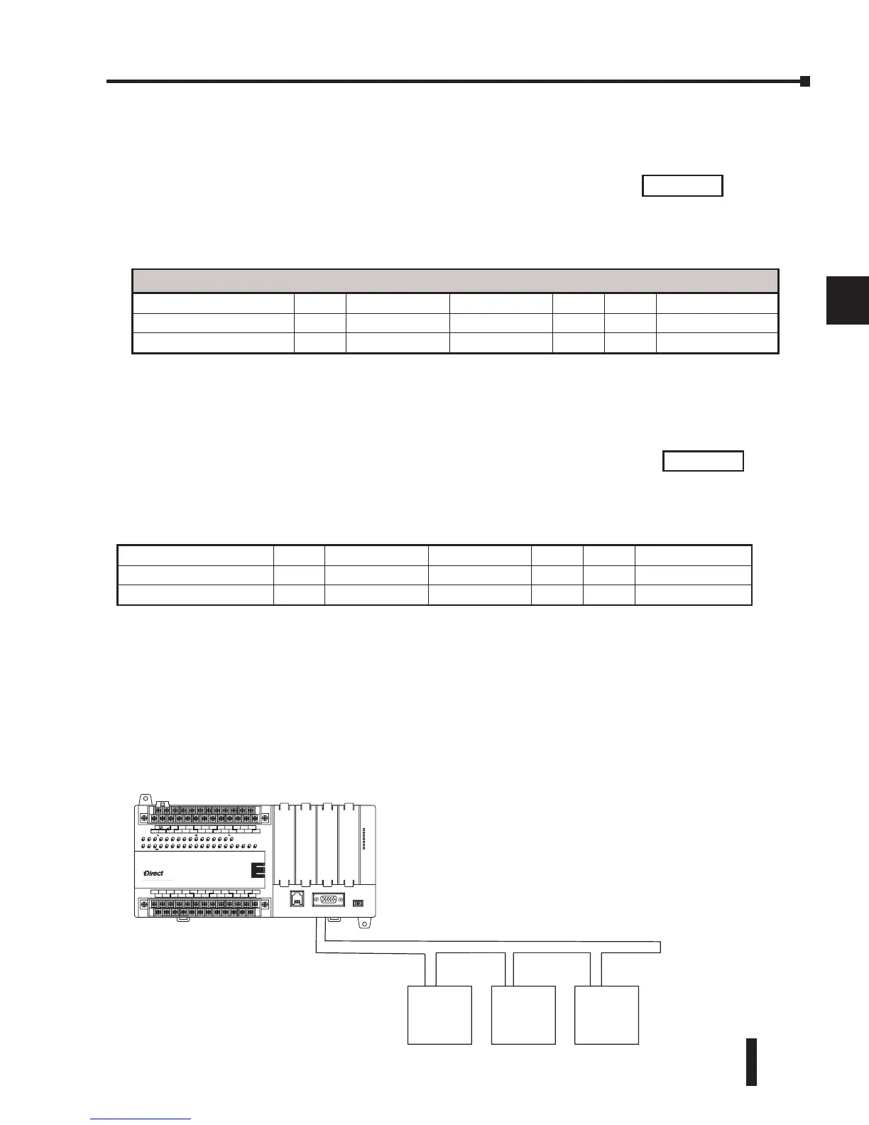
Network Master Operation
This section describes how the DL06 can communicate on a MODBUS or DirectNET
network as a master. For MODBUS networks, it uses the MODBUS RTU protocol, which
must be interpreted by all the slaves on the network. Both MODBUS and DirectNet are single
master/multiple slave networks. The master is the only member of the network that can initiate
requests on the network. This section teaches you how to design the required ladder logic for
network master operation.
For Word Data Types.... PLC Address (Dec.) + Appropriate Mode Address
Timer Current Values (V) 128 V0 – V177 0 – 127 3001 30001 Input Register
Counter Current Values (V) 128 V1200 – V7377 512 – 639 3001 30001 Input Register
V-memory, user data (V) 1024 V2000 – V3777 1024 – 2047 4001 40001 Holding Register
Outputs (Y) 320 Y0 – Y477 2048 – 2367 1 1 Coil
Control Relays (CR) 256 C0 – C377 3072 – 3551 1 1 Coil
Timer Contacts (T) 128 T0– T177 6144 – 6271 1 1 Coil
3009
3117
Slave #1 Slave #3
Master
M
Slave #2
LOGIC
Koyo
06
C0 C4C2X1 X3 X4 X6 X11X13 X14X16 X21X23 N.C.
C1 C3X2 X5 X7 X10X12
X15 X17X20 X22X0 N.C.
AC
(
N
)
24V
0V
N.C.
C1 C3Y0 Y15Y12Y10Y17Y7Y5Y2
C0 C2 Y16Y14Y13Y11Y6Y4Y3Y1
LGG
AC
(
L
)
D0-06DR
2.0AOUTPUT: 6-240V 50 - 60Hz 2.0A,6 - 27V
INPUT: 12 - 24V 3 - 15mA
Y
X
40VA50-60HzPWR: 100-240V
01 2345 6710 11 12 13 14 15 16 17 20 21 22 23
PORT1PORT2
TERM
RUNSTOP
PWR
RUN
CPU
TX1
RX1
TX2
RX2
 Loading...


