DL06 Micro PLC User Manual, 3rd Edition, Rev. E
5-51
Chapter 5: Standard RLL Instructions
1
2
3
4
5
6
7
8
9
10
11
12
13
14
A
B
C
D
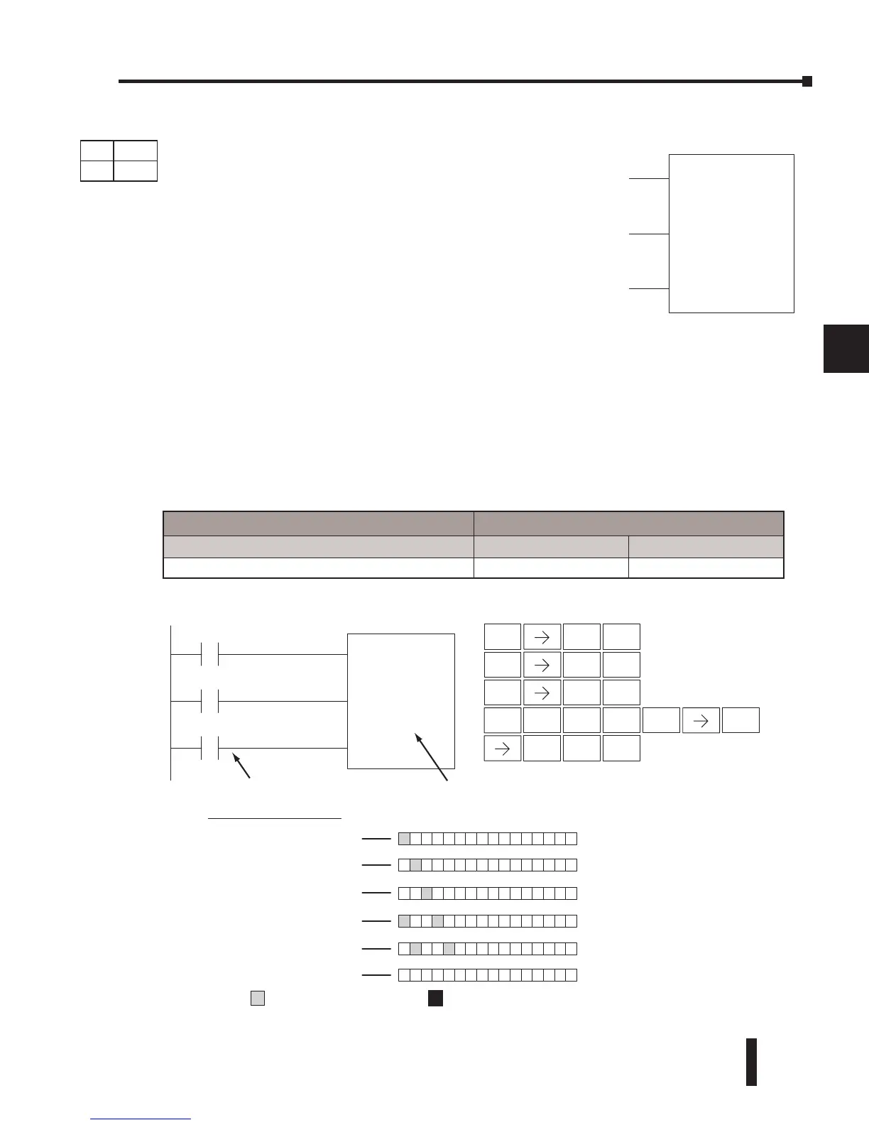
With each off-to-on transition of the clock input, the bits which make up the shift register
block are shifted by one bit position and the status of the data input is placed into the starting
bit position in the shift register. The direction of the shift depends on the entry in the From
and To fields. From C0 to C17 would define a block of sixteen bits to be shifted from left to
right. From C17 to C0 would define a block of sixteen bits to be shifted from right to left. The
maximum size of the shift register block depends on the number of available control relays. The
minimum block size is 8 control relays.
SR
aaaFrom A
bbbTo B
DATA
CLOCK
RESET
Data Input
Clock Input
Reset Input
Shift Register Bits
C0 C17
Data Reset
1 0-1-0 0
0 0-1-0 0
0 0-1-0 0
1 0-1-0 0
0 0-1-0 0
001
Inputs on Successive Scans
X1
X2
SR
C0From
C17
X3
To
Handheld Programmer KeystrokesDirect SOFT 5
STR
$
1
B
ENT
STR
$
2
C
STR
$
3
D
SHFT
ENT
ENT
RST
S
ORN
R
SHFT
0
A
1
B
7
H
ENT
SHFT
Indicates
ON
Indicates
OFF
Clock
Operand Data Type DL06 Range
A/B
aaa bbb
Control Relay C 0–1777 0–1777
DS Used
HPP Used
DirectSOFT
Shift Register (SR)
The Shift Register instruction shifts data through a predefined
number of control relays. The control ranges in the shift
register block must start at the beginning of an 8 bit boundary
and must use 8-bit blocks.
The Shift Register has three contacts.
• Data — determines the value (1 or 0) that will enter the register
• Clock — shifts the bits one position on each low to high transition
• Reset —resets the Shift Register to all zeros.



 To Next Page