DL06 Micro PLC User Manual, 3rd Edition, Rev. E
5-52
Chapter 5: Standard RLL Instructions
1
2
3
4
5
6
7
8
9
10
11
12
13
14
A
B
C
D
Accumulator/Stack Load and Output Data Instructions
Using the Accumulator
The accumulator in the DL06 internal CPUs is a 32-bit register which is used as a temporary
storage location for data that is being copied or manipulated in some manner. For example, you
have to use the accumulator to perform math operations such as add, subtract, multiply, etc.
Since there are 32 bits, you can use up to an 8-digit BCD number. The accumulator is reset to
0 at the end of every CPU scan.
Copying Data to the Accumulator
The Load and Out instructions and their variations are used to copy data from a V-memory
location to the accumulator, or to copy data from the accumulator to V-memory. The following
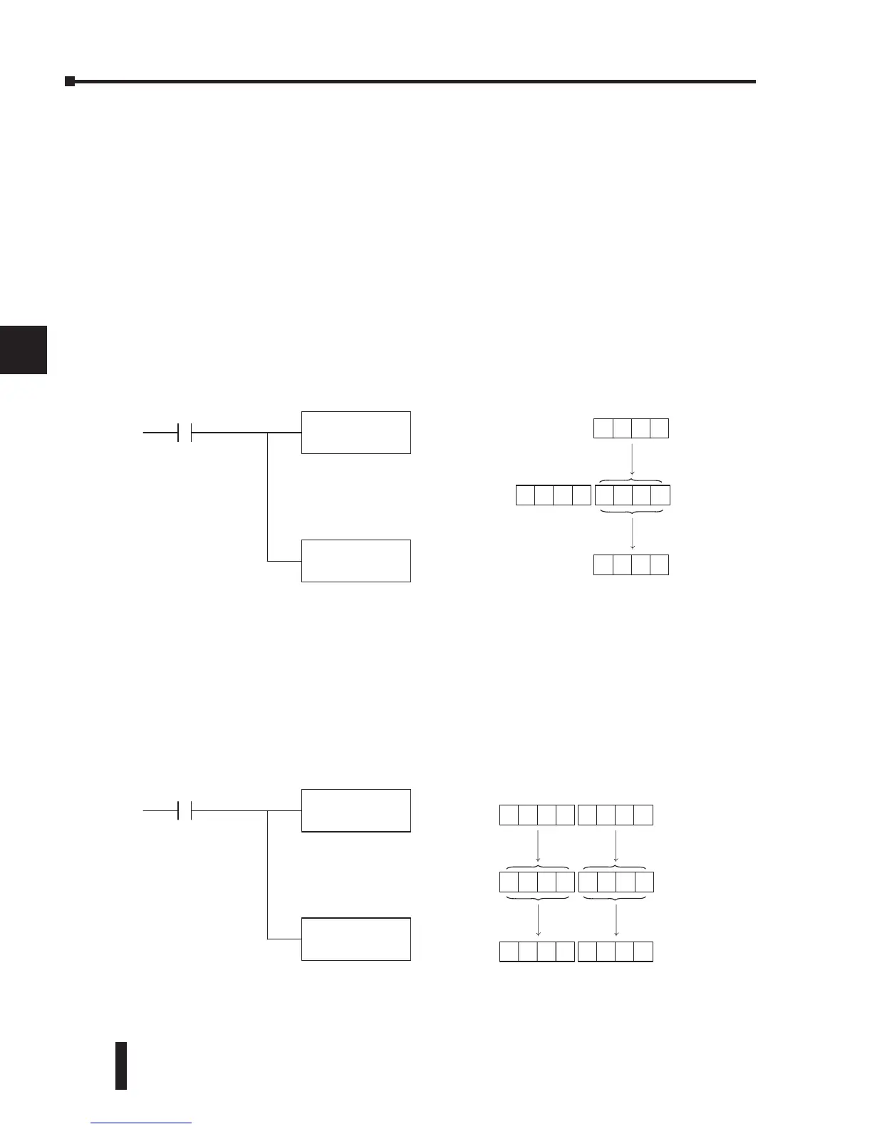
example copies data from V-memory location V2000 to V-memory location V2010.
Since the accumulator is 32 bits and V-memory locations are 16 bits, the Load Double
and Out Double (or variations thereof) use two consecutive V-memory locations or 8 digit
BCD constants to copy data either to the accumulator from a V-memory address or from a
V-memory address to the accumulator. For example, if you wanted to copy data from V2000
and V2001 to V2010 and V2011 the most efficient way to perform this function would be as
follows:
LD
V2000
X1
Copy data from V2000 to the
lower 16 bits of the accumu-
lator
Copy data from the lower 16 bits
of the accumulator to V2010
OUT
V2010
V2010
Acc.
8935
8935
00008935 8935
Unused accumulator bits
are set to zero



 To Next Page