DL06 Micro PLC User Manual, 3rd Edition, Rev. E
5-75
Chapter 5: Standard RLL Instructions
1
2
3
4
5
6
7
8
9
10
11
12
13
14
A
B
C
D
NOTE: Status flags are valid only until another instruction uses the same flag.
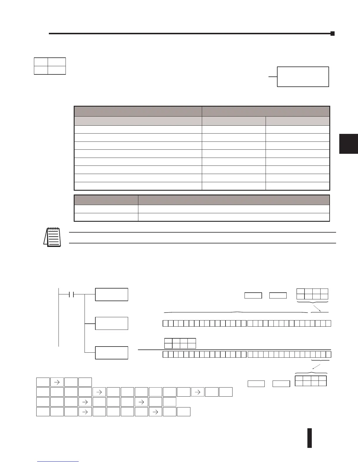
In the following example, when X1 is on, the LDF instruction loads C10–C13 (4 binary bits)
into the accumulator. The ORF instruction logically ORs the accumulator contents with Y20–
Y23 bit pattern. The ORF instruction outputs the accumulator’s lower four bits to C20–C23.
bbbK
ORFAaaa
Operand Data Type DL06 Range
A/B aaa bbb
Inputs X 0-777 - -
Outputs Y 0-777 - -
Control Relays C 0-1777 - -
Stage Bits S 0-1777 - -
Timer Bits T 0-377 - -
Counter Bits CT 0-177 - -
Special Relays SP 0-777 - -
Constant K - 1-32
X1
K4C10
00000000000001100000000000000000
15 14 13 12 11 10 98765 4 3210
31 30 29 28 27 26 25 24 23 22 21 20 19 18 17 1631 30 29 28 27 26 25 24 23 22 21 20 19 18 17 16
Acc.
Y20Y21Y22Y23
The unused accumulatorbitsare settozero
OR (Y20 --Y23)
0000000000001110
1000
000000000000
0
00 0Acc.
Constant
C20
K4
ON ON
ON
OFF
OFF
OFFON ON
C13 C12 C11 C10
C23 C22 C21 C20
ON OFF OFF OFF
Location
Constant
Location
LDF C10
K4
ORF Y20
K4
OUTF C20
K4
Load the status fo 4
consecutive bits (C10-C13)
into the accumulator
OR the binary bit pattern
(Y20 - Y23) with the value in
the accumulator
Copy the specified number
of bits from the accumulator
to C20-C23
Handheld Programmer Keystrokes
1
B
ENT
1
B
4
E
0
A
0
A
ENT
STR
$
SHFT
ANDST
L
3
D
OUT
GX
SHFT
5
F
5
F
OR
Q
SHFT
5
F
NEXT NEXT NEXT NEXT
NEXT
2
C
4
E
ENT
PREV PREV
0
A
2
C
4
E
ENT
Discrete Bit Flags Description
SP63 ON if the result in the accumulator is zero.
SP70 ON if the result in the accumulator is negative
DS Used
HPP Used
DirectSOFT
Or Formatted (ORF)
The ORF instruction logically ORs the binary value in the
accumulator and a specified range of discrete bits (1–32). The
instruction requires a starting location (Aaaa) and the number of
bits (Kbbb) to be ORed. Discrete status flags indicate if the result is
zero or negative (the most significant bit =1).



 To Next Page