DL06 Micro PLC User Manual, 3rd Edition, Rev. E
Chapter 2: Installation, Wiring, and Specifications
1
2
3
4
5
6
7
8
9
10
11
12
13
14
A
B
C
D
2-21
Relay Outputs – Transient Suppression for Inductive Loads in a Control
System
The following pages are intended to give a quick overview of the negative effects of transient
voltages on a control system and provide some simple advice on how to effectively minimize
them. The need for transient suppression is often not apparent to the newcomers in the
automation world. Many mysterious errors that can afflict an installation can be traced back
to a lack of transient suppression.
What is a Transient Voltage and Why is it Bad?
Inductive loads (devices with a coil) generate transient voltages as they transition from being
energized to being de-energized. If not suppressed, the transient can be many times greater
than the voltage applied to the coil. These transient voltages can damage PLC outputs or other
electronic devices connected to the circuit, and cause unreliable operation of other electronics
in the general area. Transients must be managed with suppressors for long component life
and reliable operation of the control system.
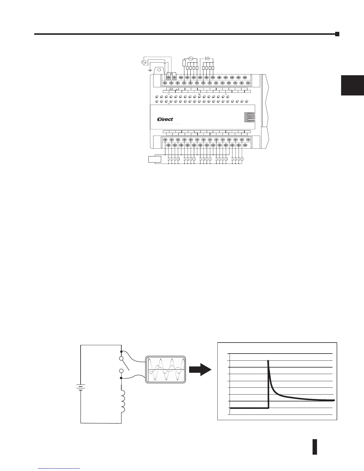
This example shows a simple circuit with a small 24V/125mA /3W relay. As you can see,
when the switch is opened, thereby de-energizing the coil, the transient voltage generated
across the switch contacts peaks at 140V.
LOGIC
Koyo
06
AC
Supply
LLLL
C0 C4C2X1 X3 X4 X6 X11 X13 X14 X16 X21 X23 N.C.
C1 C3X2 X5 X7 X10 X12 X15 X17 X20 X22X0 N.C.
LLLL
AC
(
N
)
24V
0V
N.C.
C1 C3Y0 Y15Y12Y10 Y17Y7Y5Y2
C0 C2 Y16Y14Y13Y11Y6Y4Y3Y1
LGG
AC
(
L
)
D0-06AR
40VA50-60HzPWR: 100-240V2.0AOUTPUT: 6-240V 50 - 60Hz 2.0A, 6 - 27V
Y
X
7 - 15mAINPUT: 90 - 120V
0 12345671011121314151617202122 23
fuse
+24 VDC
+
-
NL