DL06 Micro PLC User Manual, 3rd Edition, Rev. E
Chapter 2: Installation, Wiring, and Specifications
1
2
3
4
5
6
7
8
9
10
11
12
13
14
A
B
C
D
2-30
Wiring Diagrams and Specifications
The remainder of this chapter provides detailed technical information for the DL06 PLCs. A basic
wiring diagram, equivalent I/O circuits, and specification tables are laid out for each PLC.
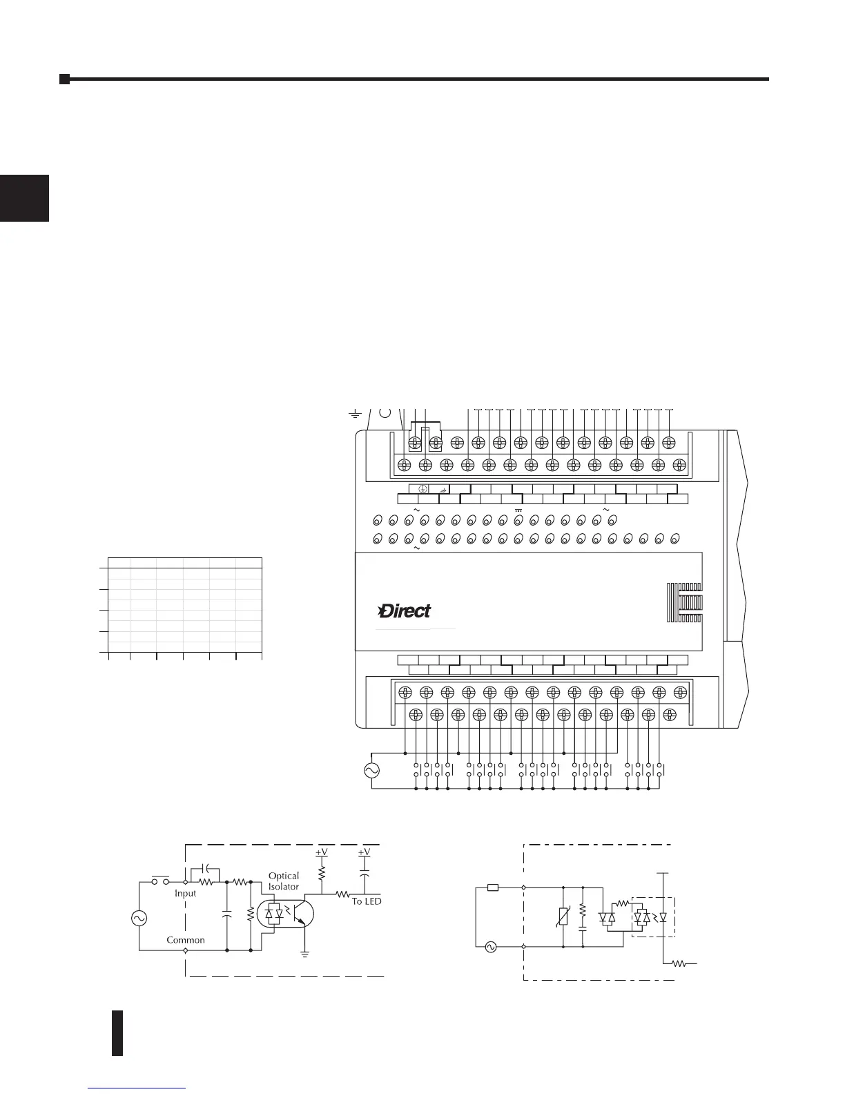
D0–06AA I/O Wiring Diagram
The D0–06AA PLC has twenty AC inputs and sixteen AC outputs. The following diagram shows a
typical field wiring example. The AC external power connection uses four terminals as shown.
Inputs are organized into five banks of four. Each bank has an isolated common terminal. The wiring
example below shows all commons connected together, but separate supplies and common circuits
may be used. The equivalent input circuit shows one channel of a typical bank.
Outputs are organized into four banks of four triac switches. Each bank has a common terminal. The
wiring example below shows all commons connected together, but separate supplies and common
circuits may be used. The equivalent output circuit shows one channel of a typical bank.
LOGIC
Koyo
06
AC
(
N
)
24V
0V
N.C.
C1 C3Y0 Y15Y12Y10 Y17Y7Y5Y2
C0 C2 Y16Y14Y13Y11Y6Y4Y3Y1
LGG
AC
(
L
)
D0-06AA
40VA50-60HzPWR: 100-240V2.0AOUTPUT: 6-240V 50 - 60Hz 2.0A, 6 - 27V
Y
X
7 - 15mAINPUT: 90 - 120V
0 12345671011121314151617202122 23