DL06 Micro PLC User Manual, 3rd Edition, Rev. E
Chapter 2: Installation, Wiring, and Specifications
1
2
3
4
5
6
7
8
9
10
11
12
13
14
A
B
C
D
2-32
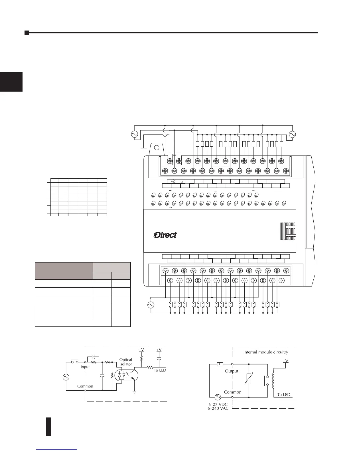
D0–06AR I/O Wiring Diagram
The D0–06AR PLC has twenty AC inputs and sixteen relay contact outputs. The following
diagram shows a typical field wiring example. The AC external power connection uses four
terminals at the left as shown.
The twenty AC input channels use terminals on the bottom of the connector. Inputs are
organized into five banks of four. Each bank has a common terminal. The wiring example
below shows all commons connected together, but separate supplies and common circuits may
be used. The equivalent input circuit shows one channel of a typical bank.
LOGIC
Koyo
06
LLLL
C0 C4C2X1 X3 X4 X6 X11 X13 X14 X16 X21 X23 N.C.
C1 C3X2 X5 X7 X10 X12 X15 X17 X20 X22X0 N.C.
LLLLLLLL LLLL
AC
(
N
)
24V
0V
N.C.
C1 C3Y0 Y15Y12Y10 Y17Y7Y5Y2
C0 C2 Y16Y14Y13Y11Y6Y4Y3Y1
LGG
AC
(
L
)
D0-06AR
40VA50-60HzPWR: 100-240V2.0AOUTPUT: 6-240V 50 - 60Hz 2.0A, 6 - 27V
Y
X
7 - 15mAINPUT: 90 - 120V
0 12345671011121314151617202122 23
OUTPUT point wiring
6-240
VAC
or
6-27
VDC
POWER
input wiring
100-240V
VAC
INPUT point wiring
90-120V
VAC
0
4
12
16
Points
Ambient Temperature (
˚C/˚F)
0
32
10
50
20
68
30
86
40
104
50
122
55˚C
131˚F
Y0 - Y7
2.0A
Y10 - Y17
8
Derating Chart for Relay Outputs
9$&
Equivalent Input Circuit Equivalent Output Circuit
Typical Relay Life (Operations) at
Room Temperature
Voltage & Load
Type
Load Current
At 1A At 2A
24VDC Resistive 500K 250K
24VDC Inductive 100K 50K
110VAC Resistive 500K 250K
110VAC Inductive 200K 100K
220VAC Resistive 350K 200K
220VAC Inductive 100K 50K