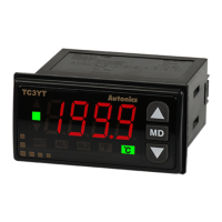
DUAL INDICATOR TEMPERATURE CONTROLLER
TCN4 SERIES
M A N U A L
Thank you very much for selecting Autonics products.
For your safety, please read the following before using.
1. In case of using this unit with machinery (Ex: nuclear power control, medical equipment, ship,
vehicle, train, airplane, combustion apparatus, safety device, crime/disaster prevention
equipment, etc) which may cause damages to human life or property, it is required to install
fail-safe device.
It may cause a fire, human injury or damage to property.
2. Install the unit on a panel.
It may cause electric shock.
3. Do not connect, inspect or repair this unit when power is on.
It may cause electric shock.
4. Wire properly after checking terminal number.
It may cause a fire.
5. Do not disassemble the case. Please contact us if it is required.
It may cause electric shock or a fire.
Caution for your safety
Ordering information
Specifi cation
Dimensions Connections
1)TCN4S
1)TCN4S 2)TCN4M
Parts description
Input sensor and temperature range
Warning
Please keep these instructions and review them before using this unit.
Please observe the cautions that follow;
Serious injury may result if instructions are not followed.
The following is an explanation of the symbols used in the operation manual.
Caution: Injury or danger may occur under special conditions.
1. This unit shall not be used outdoors.
It may shorten the life cycle of the product or cause electric shock.
2. When connect wire, AWG 20(0.50mm
2
) should be used and screw bolt on terminal block with
0.74N.m to 0.90N.m strength.
It may cause a malfunction or fire due to contact failure.
3. Please observe the rated specifications.
It may shorten the life cycle of the product and cause a fire.
4. Do not use beyond of the rated switching capacity of relay contact.
It may cause insulation failure, contact melt, contact failure, relay broken and fire etc.
5. In cleaning unit, do not use water or organic solvent. And use dry cloth.
It may cause electric shock or a fire.
6. Do not use this unit in place where there are flammable or explosive gas, humidity, direct ray
of the light, radiant heat, vibration and impact etc.
It may cause a fire or an explosion.
7. Do not inflow dust or wire dregs into the unit.
It may cause a fire or a malfunction.
8. Please wire properly after checking the terminal polarity when connecting temperature sensor.
It may cause a fire or an explosion.
9. In order to install the units with reinforced insulation, use the power supply unit which basic
insulation level is ensured.
Caution
The above specifications are subject to change without notice.
T4S24RCN
R
Relay contact output + SSRP output (AC power)
Relay contact output + SSR output (AC/DC power)
2 24VAC 50/60Hz, 24-48VDC
4 100-240VAC 50/60Hz
2 Alarm1 + Alarm2 output
S DIN W48 X H48mm
M DIN W72 X H72mm
H DIN W48 X H96mm
L DIN W96 X H96mm
4 4Digit(9999)
CN Dual display type, set by touch switch
T Temperature controller
Item
Setting type
Digit
Size
Sub output
Power supply
Control output
Series TCN4S TCN4M TCN4H TCN4L
Power
supply
AC Power
100-240VAC 50/60Hz
AC/DC Power
24VAC 50/60Hz, 24-48VDC
Allowable voltage range
90 to 110% of rated voltage
Power consumption
Max. 5VA(100-240VAC 50/60Hz, 24VAC 50/60Hz)
Max. 3W(24-48VDC)
Display method 7 Segment LED(PV: Red, SV: Green)
Character
size
PV(WXH) 7.0 X 15.0mm 9.5 X 20.0mm 7.0 X 14.6mm 11.0 X 22.0mm
SV(WXH) 5.0 X 9.5mm 7.5 X 15.0mm 6.0 X 12.0mm 7.0 X 14.0mm
Input
type
RTD
DIN Pt100Ω, Cu50Ω (Allowable line resistance max.5Ω per a wire)
TC K(CA), J(IC), L(IC), T(CC), R(PR), S(PR)
Display
accuracy
1
RTD
Based on room temperature (23ºC ± 5ºC): (PV ± 0.5% or ±1ºC higher one) rdg ± 1 Digit
In case of out of room temperature range: (PV ± 0.5% or ±2ºC higher one) rdg ± 1Digit
TC
Control
output
Relay 250VAC 3A 1a
SSR 12VDC
±2V 20mA Max.
Alarm output AL1, AL2 Relay: 250VAC 1A 1a
Control method ON/OFF control, P, PI, PD, PID control
Hysteresis 1 to 100
ºC
/0.1 to 50.0
ºC
Proportional band(P) 0.1 to 999.9
ºC
Integral time(I) 0 to 9999 sec.
Derivative time(D) 0 to 9999 sec.
Control period(T) 0.5 to 120.0 sec.
Manual reset 0.0 to 100.0%
Sampling period 100ms
Dielectric
strength
AC power
2000VAC 50/60Hz 1min.(Between input terminal and power terminal)
AC/DC power
1000VAC 50/60Hz 1min.(Between input terminal and power terminal)
Vibration
0.75mm amplitude at frequency of 5 to 55Hz in each X, Y, Z directions for 2 hours
Relay life
cycle
Control output
Mechanical: Min. 5,000,000 operations, Electrical: Min. 200,000 operations (250VAC 3A resistive load)
Alarm output
Mechanical: Min. 5,000,000 operations, Electrical: Min. 300,000 operations (250VAC 1A resistive load)
Insulation resistance Min. 100MΩ(at 500VDC megger)
Noise immunity
Square-wave noise by noise simulator(pulse width 1
㎲
)
±
2KV R-phase and S-phase
Memory retention Approx. 10 years (When using non-volatile semiconductor memory type)
Environ
-ment
Ambient
Temperature
-10 to 50
ºC
, Storage: -20 to 60
ºC
Ambient
humidity
35 to 85%RH, Storage: 35 to 85%RH
Unit weight Approx. 100g Approx. 133g Approx. 124g Approx. 179g
1: For display accuracy
- In case of room temperature (23ºC ± 5ºC)
Below 200ºC of thermocouple R, S is PV ± 0.5% or ±3ºC higher one ± 1 digit
Over 200ºC of thermocouple R, S is PV ± 0.5% or ±2ºC higher one ± 1 digit
Termocouple L (IC), RTD CU50Ω is PV ± 0.5% or ±2ºC higher one ± 1 digit
- In case of out of room temperature range
Below 200ºC of thermocouple R, S is PV ± 1.0% or ±6ºC higher one ± 1 digit
Over 200ºC of thermocouple R, S is PV ± 0.5% or ±5ºC higher one ± 1 digit
RTD CU50Ω is PV ± 0.5% or ±3ºC higher one ± 1 digit
Environment resistance is rated at no freezing or condensation.
1
3
4
5
6
2
7
8
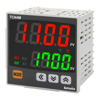
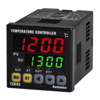
1. Present temperature (PV) display (Red)
1) RUN mode: Present temperature (PV) display
2) Parameter setting mode: Parameter display
2. Set temperature (SV) display (Green)
1) RUN mode: Set temperature (SV) display
2) Parameter setting mode: Parameter setting value display
3. Control/Alarm output display lamp
1) AL1/AL2: When AL1, AL2 alarm output ON, this lamp
turns ON.
2) OUT: When control output ON, this lamp turns ON.
During SSRP control output type in CYCLE/PHASE
control, this lamp turns ON when MV is over 3.0%.
4. Auto tuning lamp
AT lamp flashes by every 1 sec during operating auto tuning.
5.
MODE
key
Used when entering into parameter setting group, returning
to RUN mode, moving parameter, and saving setting values.
6. Adjustment
Used when entering into set value change mode, digit
moving and digit up/down.
7. Digital input key
Press
keys for 3 sec. to operate the set function
(RUN/STOP, alarm output reset, auto tuning) in digital input
key [
DI-T
].
8. Temperature unit (
ºC
/
℉
) indicator
It shows current temperature unit.
Input sensor Display
Temperature range(
ºC
) Temperature range(
℉
)
Thermorcouple
K(CA)
KCaH
-50 to 1200
-58 to 2192
KCaL
-50.0 to 999.9 -58.0 to 999.9
J(IC)
JIcH
-30 to 800 -22 to 1472
JIcL
-30.0 to 800.0 -22.0 to 999.9
L(IC)
LIcH
-40 to 800 -40 to 1472
LIcL
-40.0 to 800.0 -40 to 999.9
T(CC)
TCcH
-50 to 400 -58 to 752
TCcL
-50.0 to 400.0 -58.0 to 752.0
R(PR)
RPR
0 to 1700 32 to 3092
S(PR)
SPR
0 to 1700 32 to 3092
RTD
DPt100Ω
DPtH
-100 to 400 -148 to 752
DPtL
-100.0 to 400.0 -148.0 to 752.0
CU50Ω
CUsH
-50 to 200 -58 to 392
CUsL
-50.0 to 200.0 -58.0 to 392.0
2)TCN4M
5)Terminal cover(Sold separately)
6)Panel cut-out
4)TCN4L
D
A
B
C
ABC D
TCN4S Min. 65 Min. 65 45 45
TCN4M Min. 90 Min. 90 68 68
TCN4H Min. 65 Min. 115 45 92
TCN4L Min. 115 Min. 115 92 92
+0.6
-0
+0.7
-0
+0.7
-0
+0.8
-0
+0.8
-0
+0.8
-0
Model
Unit
[Unit: mm]
B' RTD TC
-
+
B
A
B' RTD TC
-
+
B
A
SOURCE
※2
1: 12VDC±2V 20mA Max.
2: AC power: 100-240VAC 5VA 50/60Hz
AC/DC power: 24VAC 5VA 50/60Hz
24-48VDC 3W
Flow chart for setting group
Press
MODE
key over 3 sec in any setting group, it saves the set value and returns to RUN mode.
(Exception: Press
MODE
key once in SV setting group, it returns to RUN mode).
If no key entered for 30 sec., it returns to RUN mode automatically and the set value of parameter is
not be saved.
Press
MODE
key again within 1 sec. after returning to RUN mode, it advances of the fi rst parameter of
previous setting group.
Press
MODE
key to move next parameter.
Parameter marked in
might not be displayed depending on other parameter settings.
Set parameter as 'Parameter 2group → Parameter 1group → Setting group of set value' order
considering parameter relation of each setting group.
1: It is not displayed for AC/DC power model (TCN4 -22R).
Run mode
PAR1
IN-T MAvF
PAR2
SV setting Parameter 1group Parameter 2group
AL1
AL1 alarm termerature
AL2 alarm termerature
Input
sensor
UNIT
Temperature
unit
IN-B
Input
correction
Input
digital fi lter
L-SV
SV low-limit
value
H-SV
SV high-
limit value
O-FT
Control output
operation
C-MD
Control type
OUT
Control output
type
SSrM
SSRP output
method
※
1
T
Control
cycle
AL-1
AL1 alarm
operation mode
AL-2
AL2 alarm
operation mode
AHYS
Alarm output
hysteresis
LBaT
LBA
monitoring time
LBaB
LBA detection
band
DI-K
Digital input
key
ErMV
Control output MV in case
of input break error
LOC
Lock setting
AL2
AT
Auto tunung
P
Proportional band
I
Integral time
D
Derivative time
REST
Manual reset
HYS
Hysteresis
MODEMODE
2sec.
Please any key among
MODE
, , ,
4sec.
1. All Parameter
Installation
TCN4S(48X48mm) series Other series
Insert product into a panel, fasten bracket by pushing with tools as shown above.
3)TCN4H
+
-
+
-
+
-
Warning
Caution
Product may be damaged, or injury may result if instructions are not
followed.
Terminal
cover
Terminal
cover
Terminal
cover
Terminal
cover
MODE
3sec.
MODE
3sec.
22