Do you have a question about the Autonics TCN Series and is the answer not in the manual?
Instructions to prevent serious injury or death, including fail-safe devices and proper installation.
Instructions to prevent minor injury or product damage, covering wiring, cleaning, and environment.
Highlights include dual display, high-speed sampling, relay/SSR output, and compact design for easy reading.
Covers polarity checks, noise prevention, power supply, heat radiation, and proper use for temperature control.
Guide to understanding the TCN4 product model number structure for ordering.
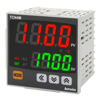
Description of the red PV display and green SV display during RUN and Setting modes.
Explains indicators like AL1/AL2, OUT, AT, and the displayed unit (°C, °F, %).
Details the function of the input keys for navigation and value setting.
Lists common error codes like OPEN, HHHH, and LLLL with their causes.
Provides guidance on checking input sensor status for troubleshooting.
Explains how to navigate between SV setting, Parameter groups, and RUN mode.
Covers settings for AL1/AL2 alarm, auto tuning, proportional band, integral, derivative, manual reset, and hysteresis.
Settings for input specification, temperature unit, filter, SV limits, control mode, and type.
Details alarm operation modes (deviation, absolute value) and option settings for latch and standby.
Configuration for SSR drive output type, LBA settings, digital input key, and parameter lock.
Describes how deviation and absolute value alarms operate based on PV, SV, and set limits.
Explains standby sequences and alarm latch behavior for different alarm conditions.
The Autonics TCN Series Dual Display PID Temperature Controllers are advanced devices designed for precise temperature management across various industrial applications. These controllers offer a comprehensive suite of features for accurate monitoring, control, and maintenance, ensuring optimal performance and reliability.
The TCN Series controllers are primarily designed for temperature regulation, utilizing a dual digital display to simultaneously show the Process Value (PV) and Set Value (SV). This allows operators to monitor the current temperature and the desired setpoint at a glance, facilitating quick adjustments and oversight. The controllers support a wide range of input types, including various thermocouples (K, J, L, T, R, S) and RTD sensors (Cu50Ω, DPt100Ω), making them versatile for different temperature sensing requirements.
At the core of their functionality is the Proportional-Integral-Derivative (PID) control algorithm, which enables highly accurate and stable temperature control. Beyond PID, the controllers also offer ON/OFF control, providing flexibility for simpler applications where precise modulation is not critical. For SSR drive outputs, advanced control options such as cycle control and phase control are available, allowing for fine-tuned power delivery to heating or cooling elements. This capability is particularly useful in applications requiring precise power management to maintain stable temperatures.
The alarm functions are extensive, offering various modes to alert operators to abnormal conditions. These include deviation high/low limit alarms, deviation high/low reverse alarms, and absolute value high/low limit alarms. Additionally, the controllers feature sensor break alarms, which activate if the input sensor is disconnected or faulty, and loop break alarms (LBA), which detect issues within the control loop itself. These diverse alarm options enhance safety and allow for prompt intervention to prevent process disruptions or damage.
Auto-tuning functionality simplifies the setup process by automatically calculating optimal PID parameters for a given system. This feature reduces the need for manual tuning, saving time and ensuring efficient control performance. The digital input key provides a flexible mechanism for external control, allowing for functions like stopping control output, resetting alarms, or initiating auto-tuning.
The TCN Series controllers are designed for ease of use and integration into existing systems. Their compact design makes them suitable for installation in control panels, while large display panels ensure excellent readability of both PV and SV, even from a distance. The dual digital display, with red for PV and green for SV, provides clear visual distinction, enhancing operational clarity.
Wiring is made convenient through different terminal types. While standard bolt terminals are available, connector plug types (TCN4S-P) offer easier wiring and maintenance, simplifying installation and reducing downtime during service. This modular approach allows for quick disconnection and reconnection of the unit without disturbing the entire wiring setup.
The controllers incorporate a high-speed sampling rate of 100ms, ensuring rapid response to temperature changes and maintaining tight control over the process. A display accuracy of ±0.5% further contributes to reliable temperature management, providing confidence in the displayed values.
Various control output modes are available, including heating and cooling, which can be selected based on the application's requirements. The ability to switch between relay output and SSR drive output (a patented feature) provides flexibility in choosing the appropriate control mechanism for different loads and control strategies. This adaptability allows the controller to be used in a wide range of heating and cooling applications, from simple ON/OFF control to more complex proportional control with solid-state relays.
The manual reset function for PID control allows operators to manually adjust the control output, providing an override capability for specific operational needs. Input correction features enable fine-tuning of sensor readings to compensate for any inaccuracies, ensuring that the displayed temperature is as close to the actual temperature as possible. An input digital filter helps to stabilize readings by smoothing out noisy input signals, which is particularly useful in electrically noisy environments.
Designed for long-term reliability, the TCN Series controllers include features that simplify maintenance and extend product lifespan. The memory retention capability ensures that all parameter settings are preserved for approximately 10 years, even in the event of power loss. This non-volatile semiconductor memory eliminates the need for reprogramming after power interruptions, reducing setup time and potential errors.
The robust construction and adherence to safety standards, including CE, cULus, and EAC approvals, ensure that the devices are built to withstand industrial environments. However, specific environmental considerations are outlined to prevent damage and ensure safe operation. These include avoiding exposure to flammable/explosive/corrosive gases, high humidity, direct sunlight, radiant heat, vibration, impact, or salinity.
For cleaning, the use of a dry cloth is recommended, and operators are advised against using water or organic solvents to prevent electric shock or damage to the unit. Keeping the product free from metal chips, dust, and wire residue is crucial for preventing malfunctions and ensuring proper operation.
The modular design, particularly with connector plug types, facilitates easier replacement or servicing of the unit. In the event of a malfunction, the unit can be quickly disconnected and replaced, minimizing downtime. The product manual provides detailed instructions for installation, wiring, and parameter settings, serving as a comprehensive guide for both initial setup and ongoing maintenance. Troubleshooting information is also included to assist operators in diagnosing and resolving common issues, such as sensor disconnections or out-of-range readings.
| Sampling Cycle | 100 ms |
|---|---|
| Control Method | PID control |
| Input Type | Thermocouple (K, J, R, S, T, B, E, N) |
| Output Type | Relay |
| Power Supply | AC 100~240V, 50/60Hz or DC 24V |
| Communication | RS485 (Modbus RTU) |
| Control Algorithm | PID |
| Accuracy | ±0.3% of full scale ±1 digit |
| Resolution | 0.1°C/°F or 1°C/°F (selectable) |