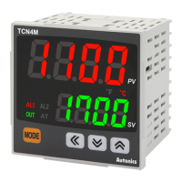
Connections
TM2
DIGITAL
INPUT
OUT1
SSR
OUT2
SSR
AL1
AL2
CONTROL
CIRCUIT
ADC
ADC
ADC
ADC
1
2
4
14
9
10
11
12
19
20
21
22
A
A
RTD
RTD
DI-1
CT2
CT1
DI-2
TC
TC
-
-
CH2 IN
CH1 IN
OUTPUT
CIRCUIT
OUTPUT
CIRCUIT
N
C
A -
CIRCUIT
CIRCUIT
AL3
AL4
-
-
-
-
Basic module
TM4
CONTROL
CIRCUIT
ADC
ADC
ADC
ADC
1
2
4
14
9
10
11
12
19
20
21
22
A
A
A
A
RTD
RTD
RTD
RTD
TC
TC
TC
TC
-
-
-
-
CH1 IN
CH2 IN
CH3 IN
CH4 IN
OUTPUT
CIRCUIT
N
C
A -
CIRCUIT
CIRCUIT
-
-
-
-
OUT1
SSR
OUT2
SSR
OUT3
SSR
OUT4
SSR
Basic module
•
•
•
Communication Interface
Protocol
Asynchronous
(parameter)
: 20 ms)
Start bit
Data bit
Parity bit
Address
•
0 1 2 3 4 5 6 7 9 A B C D E F
00 01 02 04 09 10 11 12 14
19 20 21 22 24 29
•
a
b
C
Terminal
number
a b c
1 to 12 10
13 to 22 10
- Installation
Precautions
•
•
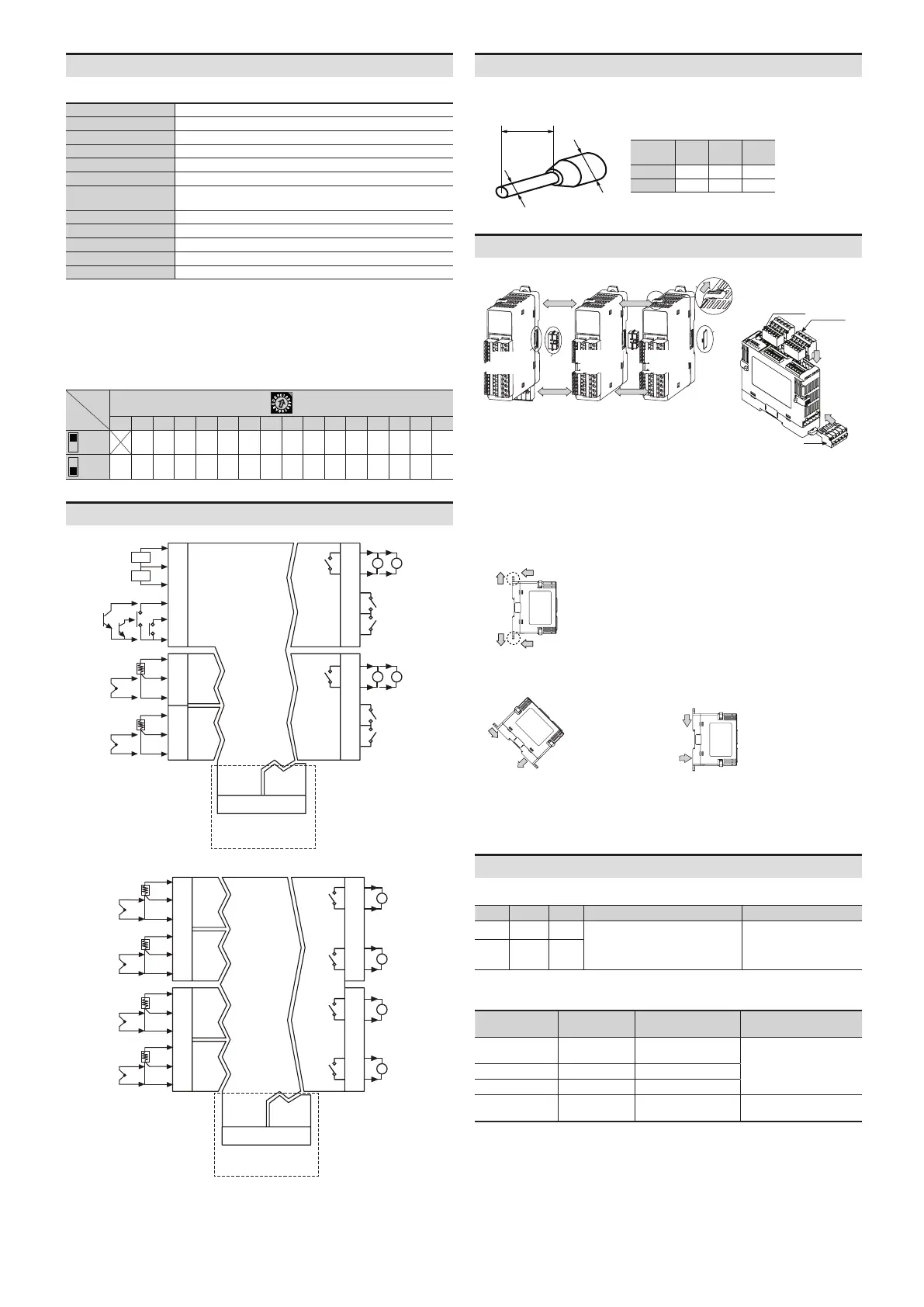
Installation Method
Connection between modules Connector
Basic
module
module
module
Sensor
input
connector
Control
output
connector
Power
Connector
•
Errors
Communication
DAQMaster
Indicator
Name Status Color
PWR ON Red
Input
internal communication error
Flash
01)
Red
 Loading...