5 6
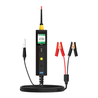
DC voltage
While the tool in this mode, contact the
probe tip to a circuit, then the LCD display
will read the DC voltage with a resolution
of 0.1 volt.
AC voltage
While the tool in this mode, contact the
probe tip to a circuit, then the LCD display
will read the Max. voltage, the Min.
voltage, frequency and duty cycle.
Resistance
While the tool in this mode, contact the probe tip to a
circuit, then the LCD display will read the resistance
between the tip and auxiliary ground lead.
Tone On/Off
While the tool in this mode, just do a quick press of
the mode button to toggle the tone on or off. While
quickly pressing (a quick press and release) the
mode button, if a short high beep is heard, this
means the audio tone is turned on. If a short low
beep is heard, the audio tone is turned off.
This function is invaluable when working in bright
areas where LED illumination alone is not sufficient.
The audio feature may be disengaged when desired,
such as for applications where the tool will be
connected to circuits for long periods of time and the
audio could become annoying.
While the tool is in DC Voltage mode, contact the
probe tip to a POSITIVE circuit. The red LED will light
and the LCD displays the voltage with a resolution of
0.1V. If the beep is turned on, a high pitched tone will
sound.
If contact the probe tip to a NEGATIVE circuit, the
green LED will light and the LCD displays the voltage
with a resolution of 0.1V. If the beep is turned on, a
low pitched tone will sound.
Voltage & Polarity Testing
Test Applications
If contact the probe tip to an OPEN circuit, neither of the LED will light.
While the tool is in Resistance mode, using the probe tip
with chassis ground or the auxiliary ground lead, continuity
can be tested on wires and components attached or
disconnected from the vehicle ’ s electrical system.
When the probe tip is contacting a good ground, the LCD
will indicate “0.0Ω ” and green LED will be on. If the tone
feature is turned on, a low pitched tone will sound.
Continuity Testing
There is also another way to prove continuity of
connections to ground or battery. Power up the connection
using the power switch. If the circuit breaker trips you know
that you have a good solid low resistance connection.
NOTE: You can use the probe tip to pierce the plastic
insulation on a wire. This means that you can test the
circuit without disconnecting anything.
In other cases, the LCD only indicates the resistance value.
If the resistance value is greater than 200kΩ , the LCD will show “0L”.
•
•
Once you extract a DTC from the vehicle and realize that troubleshooting begins with some
kind of sensor circuit, there is a quick test you can perform to verify the code. Testing your
sensor is easy while using the tool.
For example, you suspect there is a problem with your M.A.P. Sensor circuit, then follow the
procedure involved with testing this sensor:
Signal Circuit Testing