Operation and
Controls
Page 18 Avalon Vt-737sp Operation Manual
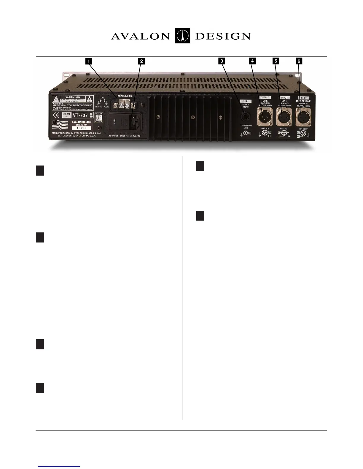
4.1 Rear Panel Description
2-terminal barrier strip. Isolates chassis
ground from audio ground. To lift ground,
simply unscrew both phillips-head screws
and remove the metal strip held down by the
screws. Do not remove this link unless you
experience hum or AC noise.
Combination IEC socket, voltage selector and
fuse location. AC Voltage is factory set as
ordered. To change the factory voltage
setting, refer to the AC Voltage Selection sec-
tion of this manual in Chapter 3 (page 13), or
contact your authorized Avalon dealer.
To change the fuse, open the cover of the AC
voltage unit and pull the fuse lever.
Unbalanced 1/4” phone jack. Used for linking
compressor sections of two Vt-737sp’s for
stereo operation.
Male XLR-3 connector, line output of unit.
Balanced DC-coupled, capable of +30dB into
600 ohms.
Female XLR-3 connector. Active input when
INPUT is set to LINE. Balanced input for line
level signals to +36dB maximum.
Female XLR-3 connector. Active input when
INPUT is set to MICROPHONE. For micro-
phone-level signals to +30dB maximum. Also
provides +48V phantom power to micro-
phone when +48V switch is engaged.
4.2 Connections
The LINE INPUTS are an electronically
balanced Class A circuit with a nominal 20k
ohm input impendance. The connectors are
female XLR-3.
The OUTPUTS are a low impendance elec-
tronically balanced circuit which terminates
to a male XLR-3 connector.
All XLR connectors are wired:
Pin 1 ground
Pin 2 high (+)
Pin 3 low (-)
1 GROUND LINK
5 LINE INPUT
6 MICROPHONE INPUT
2 AC INPUT & FUSE
3 LINK
4 LINE OUTPUT