To set IP parameters using the console port and CLI Quickstart, perform the
following tasks:
http://support.avaya.com
1-800-242-2121 (U.S.A.)
1-866 GO-AVAYA
1-866-462-8292 (US Sales)
© 2013 Avaya Inc.
Poster part number: 700507446
NN47205-304, 01.01
Recommended reading
For more information, go to http://support.avaya.com and
download the following ERS 4000 guides:
•
Locating Documentation and Regulatory Reference (NN47205-100)
•
Documentation Reference for Avaya Ethernet Routing Switch
4000 Series (NN47205-101)
•
Installing Avaya Ethernet Routing Switch 4000 Series (NN47205-300)
•
Quick Start Configuration (NN47205–104)
•
Configuring Systems (NN47205–500)
•
Release Notes (NN47205-400)
ACLI boot and factory-default commands:
boot - reboot the switch
boot default - reboot and use the factory default configuration
boot partial-default - reboot and use the partial factory default configuration
restore factory-default - reset the switch to factory default configuration
Connector Pin Number Signal
1
Ready to send (RTS) — optional, can swap or link with pin 8
2 Data terminal ready (DTR)
3 Transmit data (TXD) — mandatory
4 Carrier detect (DCD) — optional
5 Ground (GND) — mandatory
6 Receive data (RXD) — mandatory
7 Data set ready (DSR) — optional
8 Clear to send (CTS) — optional, can swap or link with pin 1
Property Value
Baud Rate 9600 bps
Data Bits 8
Stop Bits 1
Parity None
Flow Control None
Terminal emulation settings
###############################################################################
Welcome to the 4850GTS-PWR+ setup utility.
You will be requested to provide the switch basic connectivity settings.
After entering the requested info, the configuration will be applied and
stored into the switch NVRAM.
Once the basic connectivity settings are applied, additional configuration
can be done using the available management interfaces.
Use Ctrl+C to abort the configuration at any time.
###############################################################################
Please provide the Quick Start VLAN <1-4094> [1]:
Please provide the in-band IP Address[172.16.120.20]:
Please provide the in-band sub-net mask[255.255.255.0]:
Please provide the Default Gateway[172.16.120.1]:
Please provide the Read-Only Community String[**********]:
Please provide the Read-Write Community String[**********]:
Please provide the in-band IPV6 Address/Prefix_length[::/0]:
Please provide the in-band IPV6 Default Gateway[::]:
###############################################################################
Basic switch parameters have now been configured and saved.
###############################################################################
Connector Pin Number Signal
1
Carrier detect (not used)
2
Transmit Data (TXD)
3
Receive Data (RXD)
4
Data terminal ready (not used)
5
Signal ground (GND)
6
Not used
7
Request to send (not used)
8
Not used
9 Ring indicator (not used)
Setting IP parameters using the console port and CLI quick start
8
Connect the console cable to the ERS 4000
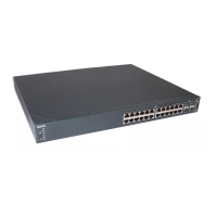
The Avaya Ethernet Routing Switch 4000 Series provides fail-safe stackability. You can
connect up to eight 4000 Series devices in a stack to provide uninterrupted connectivity
for up to 400 ports. You can manage the stack as a single unit.
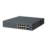
ERS 4000 series rear panel
The Avaya Ethernet Routing Switch 4000 series back panel provides a Base Unit
Select switch, Cascade Down connector, and Cascade Up connector for stacking
purposes as shown below:
Cascade Down
Cascade Up
Unit Select
Base
1 2 3
1= Cascade down connector
2= Cascade up connector
3= Base Unit Select switch
Base Unit Select switch – used to designate the base unit in a stack. When set to the
RIGHT position, this unit acts as the Base Unit for the stack. The default position for
this switch is as non-base unit.
Cascade Down and Cascade Up connectors – used to connect a switch to the next
unit in the stack through a cascade cable. Connect one end of the Cascade Down
cable to the Cascade Up connector of the next switch in the stack (shown in the
simplified stacking diagram below):
To create a stack connection, order the appropriate Avaya Ethernet Routing Switch
4000 Series cascade cables to ensure fail-safe stacking. For stacking three or more
units (maximum eight units per stack), order the 5 ft, 10 ft, 14 ft or 16.4 ft cables as
applicable (see section 2b for Order Codes).
1. Ensure that all switches for the stack are rack mounted.
2. Slide the Base Unit Select switches on the back of the units to the appropriate
position, depending on whether they are a base unit or non-base unit:
• Base Unit (Unit 1) - Slide the Base Unit Select switch to the RIGHT
• Non-Base Unit (Units 2-8) - Slide the Base Unit Select switch to the LEFT
Because stack parameters are associated with the base unit, the physical stack
order depends on the base unit position and whether you configure the stack
cascade up (stack up) or cascade down (stack down). This designation depends
on the stack cabling arrangement.
IMPORTANT: Avaya recommends you to use a Cascade Down configuration.
3. Connect stacking cables as required for a Cascade Up (stack up) or Cascade Down
(stack down) configuration as shown below:
Connect the AC power cord to the back of the switch, and then plug the other end
of the cord into an AC power outlet.
Warning: You must use a power cord set approved for the 4000 Series switch and the
power receptacle type in your country.
Check the front-panel LEDs as the device powers on to be sure the PWR LED is
lit. If not, check if the power cord is plugged in correctly.
The switch will power on immediately when it is connected to a suitable AC
power source.
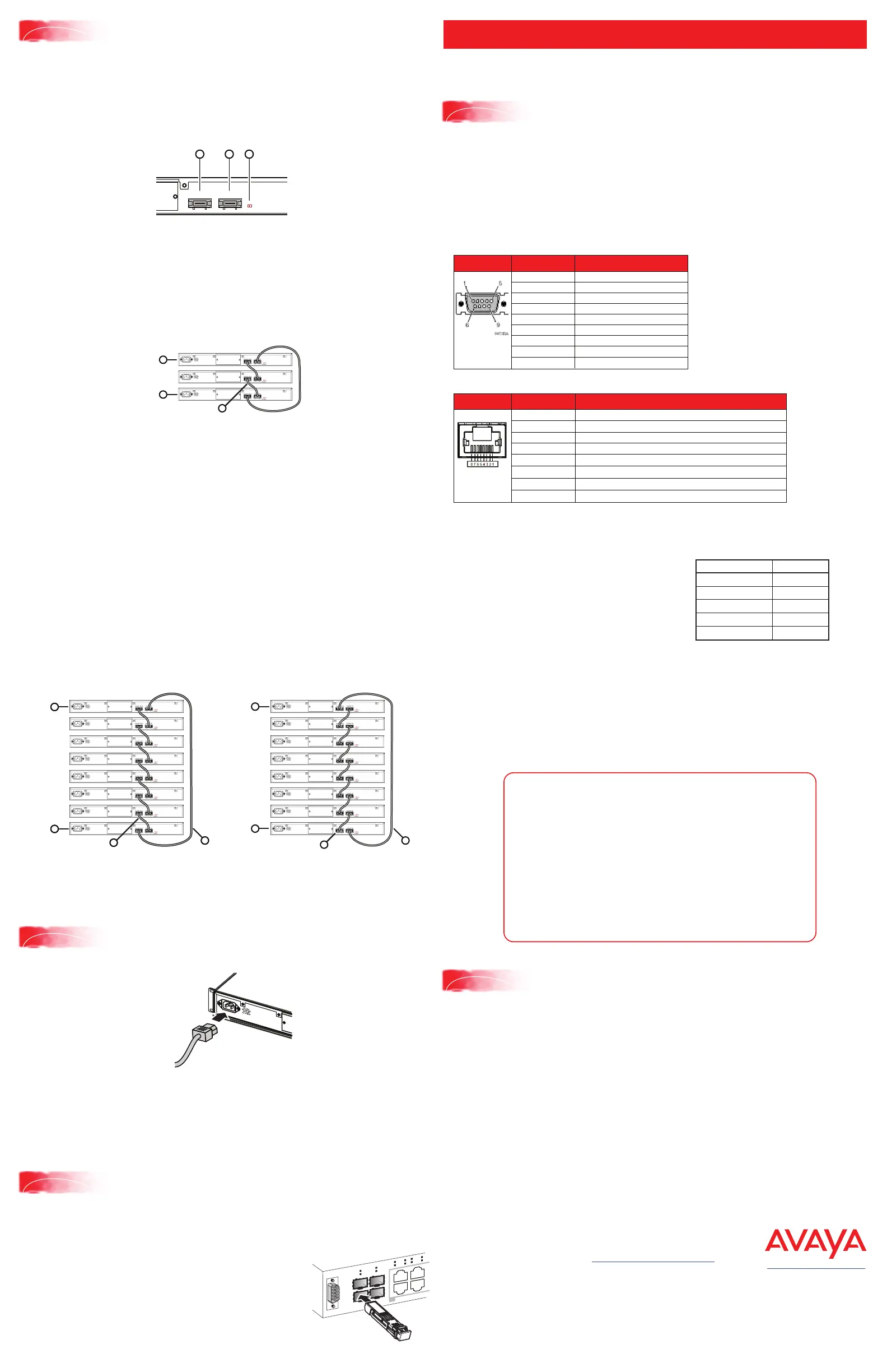
Before installing SFP and SFP+ transceivers, ensure the switch is up, fully booted, and
operating normally. Verify that the SFP or SFP+ transceivers and network cabling
support your network configuration.
Install SFP transceivers by performing this procedure.
1. Remove the transceiver from the protective packaging.
2. Verify that the transceiver is the correct model for the
network configuration.
3. Grasp the transceiver between your thumb and forefinger.
4. Insert the transceiver into the proper module on the switch.
Apply a light pressure to the transceiver until it clicks and
locks into position in the module.
3
1
2
4
PoE
Depending on your ERS 4000 switch model, the console port is either the RJ-45 port
outlined with a blue border, or the DB-9 port on the front of your ERS 4000 Series switch
(note orientation). Use an RJ-45 to DB-9 cable, or a DB-9 to DB-9 serial cable to connect
the switch console port to your management terminal. Adapters are available to provide
different connection options. The maximum length of a console cable is 25 feet (8.3
meters). The following tables describe the RJ-45 and DB-9 console port pin-out
information. You can use the pin-out information to verify or create a console cable for
use with your maintenance terminal.
DB–9 Console port pin assignments
1. Connect the console cable from the terminal to the console port of the switch to allow
initial configuration. Any terminal or PC with the appropriate terminal emulator can be
used as the management station.
2. Set the terminal protocol on the terminal
or terminal emulation program to
VT100 or VT100/ANSI.
3. Connect to the switch using the terminal
or terminal emulation application.
4. The Avaya switch banner appears when
you connect to the switch through the
Console port. There is no default password for the switch for CLI console access.
Enter Ctrl+Y and type the following CLI commands:
• enable
• install
5. The CLI Quickstart welcome screen helps you enter the information requested at
each prompt.
Note: The ERS 4000 uses the default IP address of 192.168.1.1/24 if the switch does
not get its IP address from another source.
RJ–45 Console port pin assignments
Unit 1
Unit 2
Unit 3
Unit 4
Unit 5
Unit 6
Unit 7
Unit 8
1
2
4
3
Unit 1
Unit 2
Unit 3
Unit 4
Unit 5
Unit 6
Unit 7
Unit 8
1
2
4
3
Cascade Down (Stack Down) configuration
1= Base unit
2= Last unit
3= Cascade/Stack Cable
4= Cascade/Stack Cable (Return cable to make
stack resilient. Use longer stack cable if required.)
Unit 8
Unit 1
Unit 2
Unit 3
Unit 4
Unit 5
Unit 6
Unit 7
1
2
4
3
Cascade Up (Stack Up) configuration
1= Base unit
2= Last unit
3= Cascade/Stack Cable
4= Cascade/Stack Cable (Return cable to make
stack resilient. Use longer stack cable if required.)
Unit 1
Unit 2
Unit 3
1
2
3
Simplified Stacking diagram
1= Base unit
2= Last unit
3= Cascade/Stack Cable
5
Stacking
6
Powering Up
7
Installing SFP and SFP+ transceivers
9
Connecting to the ERS 4000 embedded Web UI
1. Connect a Laptop/PC to any Ethernet port and ensure that the PC has an IP address
configured within the same IP subnet as the switch management IP address.
2. Start your web browser, such as Internet Explorer or Firefox.
3. Enter switch management IP address in the URL field and press Enter
(for example; 192.168.1.1).
4. The switch summary screen appears on your browser. Use the navigation tree on the
left to select switch configuration options.
Note: You do not need login credentials.
 Loading...