4
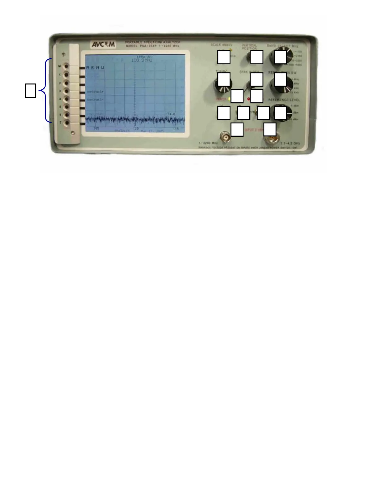
INPUTS, OUTPUTS, AND CONTROLS
Front Panel
A. BNC Jack (1—2200 MHz)
The BNC jack is used to receive signals using a whip antenna, cable, or a probe. This jack is the
RF Input jack used in conjunction with Band 1 (1—1100 MHz) and Band 2 (950—2150 MHz) of the
spectrum analyzer.
WARNING! Voltage is present on this jack when the LNA/LNB power switch is in either the 13V or 18V
position.
B. N-Type Jack (2.1—4.2 GHz)
The N-Type jack is used for receiving signals when operating in either Band 3 (2100—3200 MHz)
or Band 4 (3200—4200 MHz) of the spectrum analyzer.
WARNING! Voltage is present on this jack when the LNA/LNB power switch is in either the 13V or 18V
position.
C. POWER Switch
Use this button to turn the PSA-37XP ON or OFF
D. 22KHz Switch
This switch puts a 22KHz signal on connectors when the LNA/LNB Power is applied
E. LNA/LNB Power Switch
This switch can be placed in either the 13V or 18V position which will then provide the correct volt-
age to power an external LNA/LNB.
F. REFERENCE Level
The Reference Level control establishes the amplitude calibration for the display. This switch can
A B
C D E F
G H
I J K
L N M
O