Do you have a question about the AVCOM PSA-37XP and is the answer not in the manual?
Critical warnings and precautions for safe operation and handling of the PSA-37XP, including electrical safety.
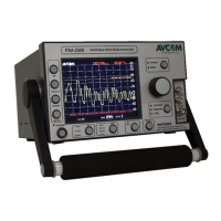
Details the BNC (1-2200 MHz) and N-Type (2.1-4.2 GHz) RF input connectors on the front panel.
Explains the function of the POWER, 22KHz, and LNA/LNB Power switches on the front panel.
Describes the function and adjustment capabilities of the Reference Level control.
Explains status lights and front panel buttons used for display adjustments and menu navigation.
Details the TUNING, SPAN WIDTH, and RESOLUTION BANDWIDTH knobs for signal adjustment.
Describes the SCALE dB/Div and VERTICLE POSITION knobs for display scaling and positioning.
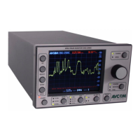
Details RS-232, MFC-XXXX, and DC INPUT JACK ports on the rear panel for communication and power.
Explains the METAL Foot, BATTERY PANEL access, and the DC FUSE for unit protection.
Describes WEB PAGE access and specific MFC .1-2.1 GHZ OUTPUT and MFC INPUT jacks on the rear panel.
Identifies the MENU buttons and the area displaying the analyzer's MODEL Number.
Describes the CENTER Frequency display and the contrast value indicator on the screen.
Explains the meaning of SPAN Width, AMPLITUDE, TIME, and DATE displays on the analyzer screen.
Details MINIMUM/MAXIMUM Frequency, CENTER Frequency, and MENU SELECTION values shown on display.
Overview of the menu structure and options available on the initial boot screen of the spectrum analyzer.
Details options for changing menus, frequency lock, and frequency counter within the startup menu.
Describes functions for ride peak, alarm settings, and display line control in startup menu 3.
Covers dB offset adjustments, increase/decrease X, and sound ON/OFF configuration in startup menu 4.
Details frequency marker operations, creating/removing markers, and saving marker information.
Explains internal MFC ON/OFF, adjustment, and external MFC reset options in startup menu 6.
Covers displaying actual time and adjusting HOUR, MINUTE, and SECOND values in startup menu 7.
Details displaying actual date and adjusting MONTH, DAY, and YEAR values in startup menu 8.
Details options for trace management (A->B, hide/view) and peak holding functionality.
Explains saving and recalling traces via memory locations 01 through 05.
Covers display options for reading units (dBm/dBmv) and toggling the grid display.
Details functions for finding peaks, frequency lock, and the frequency counter.
Explains contrast adjustment, video flip, sweep reversal, and band aid functions.
Explains the SCOM Off function for controlling serial communication.
Guides users through initial setup, power-on, and basic familiarization procedures.
Explains how to use the Band Aid feature for viewing down-converted KU-Band frequencies.
Guides on connecting and setting up an external Microwave Frequency Converter (MFC).
Instructions on how to enable, disable, and reset the internal frequency extender functionality.
Lists display, memory, connectors, adapters, power, and frequency range specifications.
Covers battery life, controls, power, accessories, dimensions, and weight.
Details RS-232 communication, SCSA interface, battery packs, and carrying case.
Explains battery capacity, discharge, temperature effects, and external power source usage.
Provides information on how batteries are shipped and their charging times and procedures.
Presents charts detailing 802.11 ISM frequency bands and Microwave Frequency Bands.
Defines various radio frequency bands including ELF, VLF, LF, MF, HF, VHF, UHF, and EHF.
Defines IEEE 802.11 standards and microwave bands like L, S, C, X, K, Ka, and Ku.
Details AVCOM's warranty coverage, exclusions, and procedures for in-warranty service.
| Input Impedance | 50 ohms |
|---|---|
| Display | LCD |
| Input Power Range | +20 dBm |
| Input VSWR | < 2:1 |
| Power Supply | +12 VDC |
| Input Connector | N-type female |