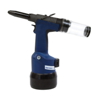
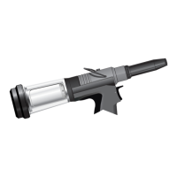
INTENSIFIER
Item numbers in bold refer to the illustration and parts list opposite.
When dismantling the intensifier assembly, first disconnect the air supply hose to intensifier inlet connector 22.
Using an Allen Key* undo four screws 27 and remove protection plate 24.
Disconnect the trigger hose (item 14 on page 24 or item 58 on page 26) from intensifier valve 42 by depressing the outer collet
and withdrawing the hose.
Remove cover plate 3 and gasket 37 by removing screws 39 and washers 38 using Allen Key*.
Ensure gasket is not damaged to ensure a proper seal on reassembly.
Invert intensifier assembly and drain oil from reservoir into a suitable container.
Remove quick release connector 33 together with connector 32 and seals 34 with a suitable spanner*.
Remove intensifier valve 42 by removing the fixing screws with a suitable spanner taking care to retain ‘O’ ring 20 located in the
Intensifier Body Casting.
Remove Screw 18 using a suitable Allen key* and remove filter cover 15, foam silencer 14, spacer 17 and retaining plate 19.
Using a screwdriver, carefully remove internal retaining ring 13. Clean and inspect groove for signs of damage.
Using Extractor*, insert male threaded end into end cover 11 and withdraw it, along with intensifier sleeve 28 and ‘O’ rings 9 and
12.
Insert Rod* through the connector orifice at the front of the intensifier body and tap out intensifier rod 8 and piston assembly.
Using a suitable Allen Key*, unscrew two screws 25 and remove end cover 11 from intensifier sleeve 28.
Remove plug 6 with a spanner*.
Insert rod* through connector orifice at the front of the intensifier body and push out seal housing 4 and ascociated ‘O’ rings.
Remove valve housing assembly 36 from the main body with a suitable spanner*. Clean by blowing through with a low pressure
air jet.
Remove piston rod 8 from intensifier air piston 10 by gripping the first 20mm (
3
/4”) of the rod in a vice fitted with soft jaws, taking
care not to damage or mark the working surface.
Unscrew locking nut 16 with a suitable spanner*.
Assemble in the reverse order of dismantling, observing the following:
Clean all parts and renew all ‘O’ rings.
Lubricate all seals using Moly lithium grease.
Valve housing assembly 36 must be refitted using a thread sealing adhesive.
Assemble the piston Assembly using a new locknut 16.
End cover 11 must be fitted correctly inside internal retaining ring 13. The tool must not be operated if the end cover has been
omitted.
28
■
■
■
■
■
■
■
■
■
■
■
■
■
■
■
■
■
■
■
■
■
■
■
■
* refers to items included in the Avdel service kit. For complete list see page 21.
I M P O R T A N T
Priming is ALWAYS necessary after the tool has been dismantled and prior to operating.