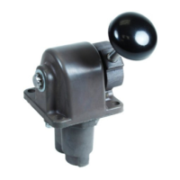
TESTING VALVE
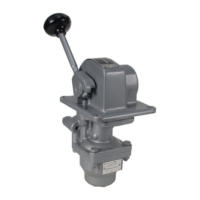
After any repair or adjustment, the HE-2 CONTROLAIR
®
Valve
should be tested using procedures and test arrangements de-
scribed in this section. Pressure control valves of this nature
should be tested for following:
1. Function
2. Pressure Range
3. Leakage
4. Flow Capacity
5. Response
6. Mechanical Detent
Some of the adjustments affecting these factors have been
described in the ‘MAJOR REPAIRS MAINTENANCE AND AD-
JUSTMENTS” section. General instructions for accomplishing
the six tests above are as follows:
1. FUNCTION: The H-2 CONTROLAIR consists of a 3-way
graduating valve with each valve having its own separate deliv-
ery line. See “DESCRIPTION OF MODELS” for valve function.
The function will be checked using the test arrangement to
insure volume (1 & 8) charged in direction of handle travel.)
2. PRESSURE RANGE: The maximum and minimum pres-
sure range generated in delivery port (8) shown on the
“IDENTITY SCHEDULE”, and is dependent upon the control
spring in use. The supply pressure present at port (2) will be
delivered at port (1) when handle is moved from “OF” to clutch
position. See pressure setting in ’ADJUSTMENT” section.
After valve is adjusted, check the 2+ minimum and maximum
pressure ranges are generated in delivery line (8) as per
‘IDENTITY SCHEDULE” by moving handle from neutral to
“FULL” travel position.
3. LEAKAGE: Set supply pressure to 20 psi (1.4 bar) above
maximum delivery pressure of valve being tested. Using soap
solution, coat the valve at pipe bracket and spring housing part-
ing lines. No leakage is permitted in any handle position.
A. Port (1) Side Valve: Set supply pressure to 100 psi (7
bar). Move valve handle to the 10 degrees “clutch” posi-
tion from “off” position to deliver supply pressure to port
(1) and hold (detent position on detented valves); close
valve in supply line to port (2) and valve in port (1) delivery
line to isolate side valve being tested. Observe delivery
pressure gage in line (1). A pressure drop of no more than
2 psi (.14 bar) in 30 seconds is permitted.
C. Port (8) Graduating Valve:
1. On all valves with spring ranges less than 100 psi (7
bar), set supply line pressure to 100 psi (7 bar).
Move valve handle to full travel position and hold
(detent position on detented valves). Close valve in
supply line to port (2) and valve. Observe delivery
pressure gage in line (8). A pressure drop of no
more than 2 psi (.14 bar) in 30 seconds is permitted.
2. On all valves with spring ranges 100 psi (7 bar) and
above, set supply line pressure to 100 psi (7 bar).
Move valve handle to deliver 95 psi (6.5 bar) to deliv
ery line (8) and hold in that position. Close valve in
supply line to port (2) and valve in port (8) delivery
line to isolate graduating valve. Observe delivery
pressure gage in line (8). A pressure drop of no
more than 2 psi (.14 bar) in 30 seconds is permitted.
4. FLOW CAPACITY: Set supply line pressure to 100 psi
(7 bar) regardless of control spring rating of valve.
A. Port (1) Side Valve: Moving the handle from “off” po-
sition to full travel position should inflate the delivery vol-
ume (1) within time limits shown in Table I.
TESTING AND TEST SET-UP
Moving handle quickly from full travel position to “off”
position should exhaust volume (1) within time limits
shown in Table I.
B. Port (8) Graduating Valve: Moving the handle
from “off” to full travel position should inflate the
delivery volume connected to port (8) within time
limits shown in Table II. Moving handle quickly from
full travel position to “off” position should exhaust
volume connected to port (8) within time limits
shown in Table II.
5. RESPONSE: Move handle to full travel position.
Fully open the valve at test volume (8) so that air ex-
hausts through the choke plug. Observe the delivery
pressure gage at volume (8). A pressure drop of no more
than 3 psi (.21 bar) is permitted.
6. MECHANICAL DETENT:
A. All models except part no. P -062062-00000 type.
Move handle from “off” to “clutch” position. Con-
nect a spring scale just below knob. A minimum
of 7 lbf. (9.5 Nm) should be required to pull from
“clutch” position toward “off” position.
B. (HE-2-LX Model Only) Move handle to extreme
detent position. Connect a spring scale just
below knob. A minimum of 12 lbf. (16 Nm)
should be required to pull handle our of detent.
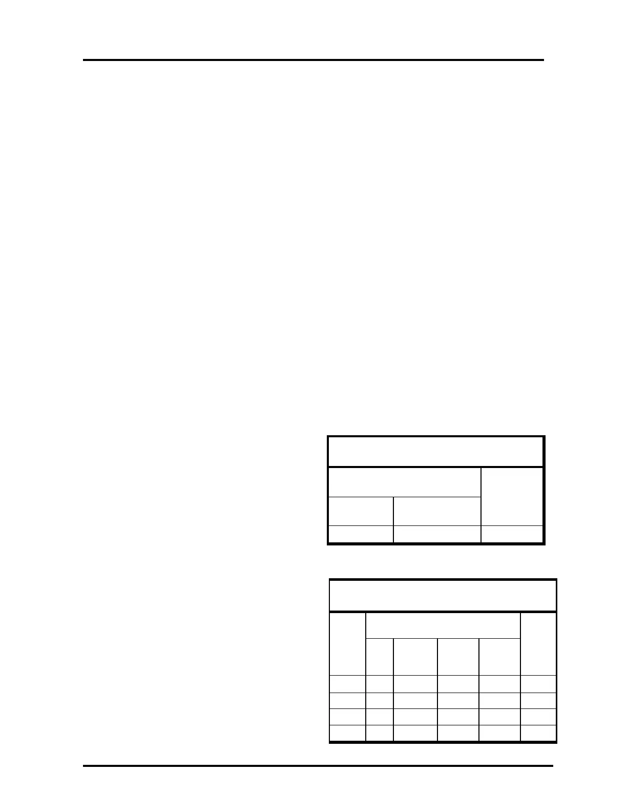
TABLE I
TEST VOL-
UME CU.
IN.
MAXIMUM
TIME “FILL”
MAXIMUM TIME
“EXHAUST”
1 SEC.
3 SEC. 225
TIME TO “FILL” AND “EXHAUST”
VOLUME
TABLE II
FLOW CAPACITY TESTS - POST 8
VALVE
SETTING
-PSI-
TESTS RANGES & TIME
FILL
PSI
MAXIMUM
TIME
SEC.
EXHAUST
PSI
MAXIMUM
TIME
SEC.
0-65
0-100 0→50 1 50→10 2 225
0-125
0-150
TEST
VOLUME
CU. IN.
Page 15


 To Next Page
 Loading...