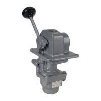
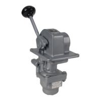
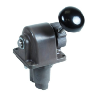
DESCRIPTION OF OPERATION
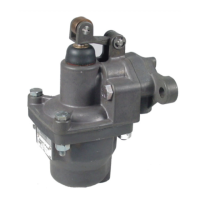
Note in the diagrammatic that supply
pressure is connected to port (2) and this supply
pressure is directed to the side control valve and
the graduating pressure control valve. The cavity
for a second side control valve is plugged. The
delivery from the side valve is directed to port (1).
The delivery from the graduating valve is directed
to port (8).
With the handle is “OFF” position port (1) is
open to atmosphere through its respective side
valve and port (8) is at zero.
The handle operates a dual cam. The cir-
cumferential surface of the cam is contoured to
provide gradual positing increments to the graduat-
ing control portion. A side cam surface deflects the
pilot lever to operate the side valve.
Movement of the handle from “OFF”,
positions the dual cam to push down the pressure
control plunger closing lower exhaust valve and
opening the upper supply valve which permits air to
flow to port (8) and the upper diaphragm chamber.
As the pressure builds up in the delivery line (8) it
acts through the sensing port orifice and deflects
the control diaphragm downward, compressing the
control spring. When sufficient diaphragm deflec-
tion is obtained to allow the upper supply valve in
pressure control portion to close, the pressure in
the delivery line is held to that valve.
The valve of the pressure delivered to the
outlet port is proportional to the pressure control
plunger movement. This movement in turn is
controlled by the cam contour and is therefore
proportional to the handle travel.
Movement of the handle to the first 10 de-
grees of the handle travel, “clutch” position, oper-
ates the 3-way side valve to connect supply “IN”
pressure to outlet port (1).
The HE-2 CONTROLAIR Valve will
automatically compensate for downstream air
pressure changes in the graduated pressure
delivery line (8). These air pressure changes
can be caused by line leakage, temperature
change or load feedback. If air pressure at the
outlet port (8) increases over that called for by
handle position, the diaphragm in the control
portion will deflect downward opening the lower
exhaust valve and exhausting air until the
original setting is obtained. If the pressure
drops below that called for by the handle
position the decreased force on the diaphragm
will allow the control spring to force the
diaphragm upward, cracking the upper supply
valve to restore the set pressure.
The range of pressure is controlled by
the strength of the diaphragm spring. Various
values are available as shown on Identity
Schedule, page 6.
Page 4