CTR 8540 GETTING STARTED: INSTALLATION
5. Install the SD card in the slot at the rear of the CTR chassis. NOTE: CTR
must be powered OFF when installing or removing the SD card.
o
The SD card holds the SW load, default/current configuration, and as-
ordered capacity and feature licenses.
n The SD card is identified by a unique serial number, which identifies
a terminal for capacity and feature license purposes. It also retains
copy of the current terminal configuration, and the previous
configuration for roll-back purposes.
n If the SD card is transferred to another terminal, the new terminal
assumes the identity of the previous terminal.
o
Insert the SD card into the slot label-side up, and carefully push-in until
it clicks home.
o
To remove the card, push-in to release.
6. Fit Ethernet RJ-45 or fiber cables as required. For fiber, first install the
required SFP option.
7. Fit E1/DS1 tributary cables as required. For information on the available
tributary cable sets, refer to the CTR 8540 Installation Guide.
8. Carry out a complete check of the installation. When checked and correct:
o
If option modules are to be installed, proceed to the next topic.
o
If no option modules are to be installed, CTR is ready for connection to
power. See Power Supply on page 9.
CAUTION: Ambient temperatures must not exceed 55
0
C (131
0
F). If
installed in a rack cabinet, it is the ambient within the cabinet.
Adding Modules to CTR
Plug-in modules are used to provide platform PSU redundancy, radio interfaces to
Aviat ODUs or IRU 600, auxiliary data and alarm services, and PoE+ RJ-45 con-
nections to external devices.
Modu les can be in st alled prior to or after in itial CTR power-on .
CAUTION: Install plug-in modules in their assigned slot positions,
and check their front panels are flush-fitted (not protruding) and
held secure by their fasteners (finger-tighten - do not over-tighten).
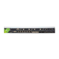
PWR Module
Install in slot 1 only to provide a backup power supply input.
Figure 1-2. PWR Module
6 AVIAT NETWORKS