CTR INSTALLATION GUIDE
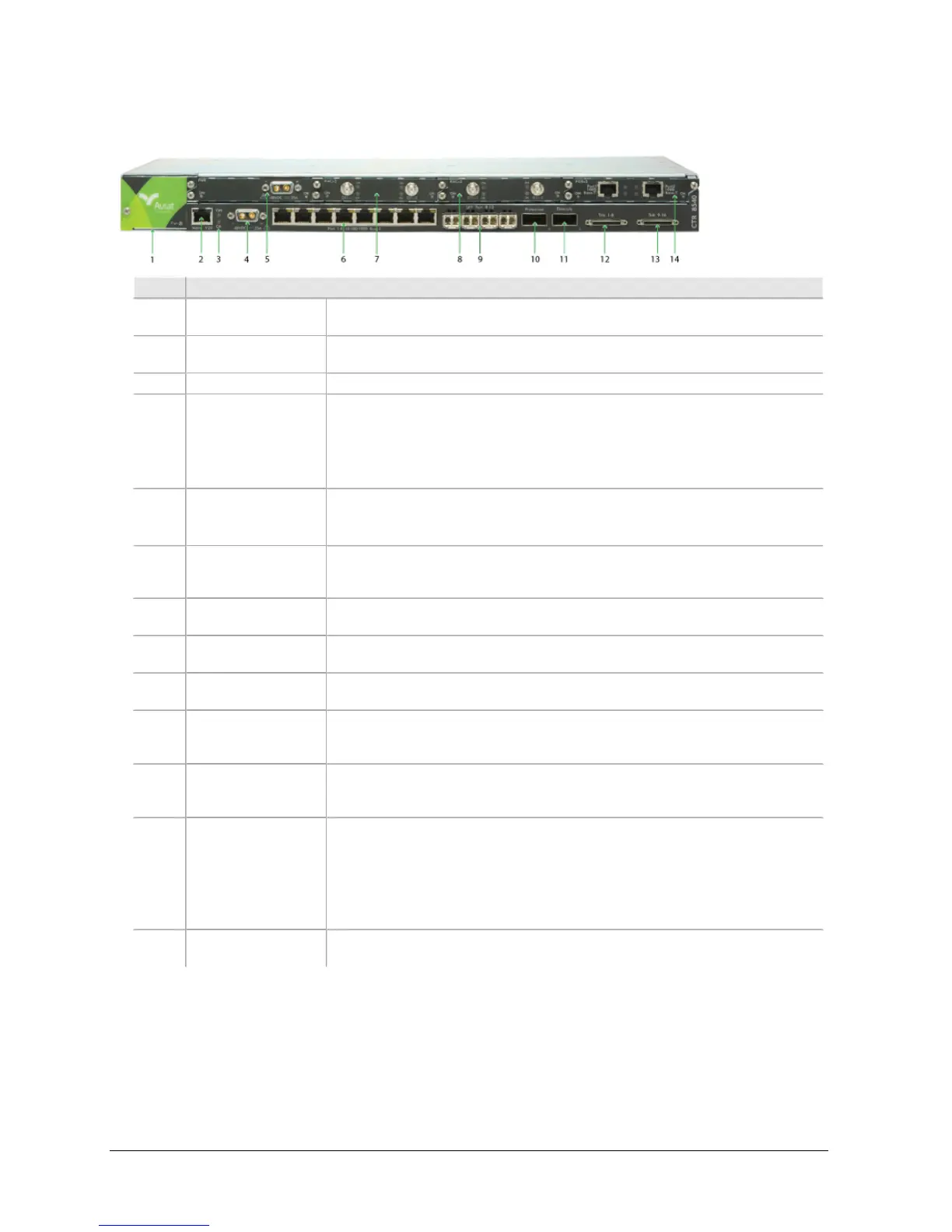
Figure 1-1. CTR 8540 Front Panel
Item Description
1 Fan Tray Fan tray houses the Fan module with four software controlled fan units. The
Fan is a compulsory module.
2 RJ-45 V24 Main-
tenance Port
Port for serial data connection of PC craft tool.
3 Status LEDs Chassis operational status.
4 Power Connector D-sub M/F 2W2 connector for -48 Vdc power supply (+ve earth).
l Operational voltage range: -40.5 to -56 Vdc.
l Connection is reverse polarity protected.
l The dc supply must be UL or IEC compliant for SELV (60 Vdc maximum
limited).
5 Slot 1. PWR module
installed.
Universal plug-in slot. Accepts all plug-in modules.
Slot 1 must be used where power supply protection is required (using the
PWR plug-in module).
6 8x Switch Ports RJ-45 10/100/1000Base-T switch ports. Each RJ-45 includes an orange Activ-
ity LED and a green Connection LED.
Port 1 is default enabled for Ethernet connection of PC craft tool.
7 Slot 2. RACx2 module
installed.
Slot accepts RAC or PoE modules.
8 Slot 3. RACx2 module
installed.
Slot accepts RAC or PoE modules.
9 4x SFP Switch Ports SFP ports (cages). SFP transceivers are available for optical or electrical con-
nection.
10 Protection Port Quad SFP port (cage). A Protection cable comprising back-to-back to con-
nected optical Quad SFPs is installed between CTR chassis to enable cross-
chassis protection and switch stacking.
11 Diversity Port Quad SFP port (cage). A Diversity cable comprising back-to-back to connected
optical Quad SFPs is installed between CTR chassis to enable space or fre-
quency diversity on cross-chassis radio link pairings.
12, 13 Trib. connectors HDR connectors for tributary cable connection. Service supports:
l 16xE1 or 16xDS1 (8x per connector).
l 75 ohm unbalanced or 120 ohms balanced on E1 tribs.
l Individual line code selection for AMI or B8ZS on balanced 100 ohm DS1
tribs.
l Mapping to E1/DS1 pseudowires (CESoETH, unstructured).
14 Slot 4. PoEx2 module
installed.
Slot accepts RAC or PoE modules.
Installation Requirements
This table lists cautions, rules, and guides for CTR chassis installation.
260-668240-001 DECEMBER 2014 3