CTR 8540 GETTING STARTED: INSTALLATION
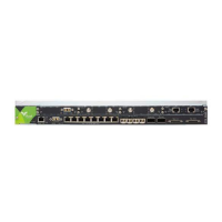
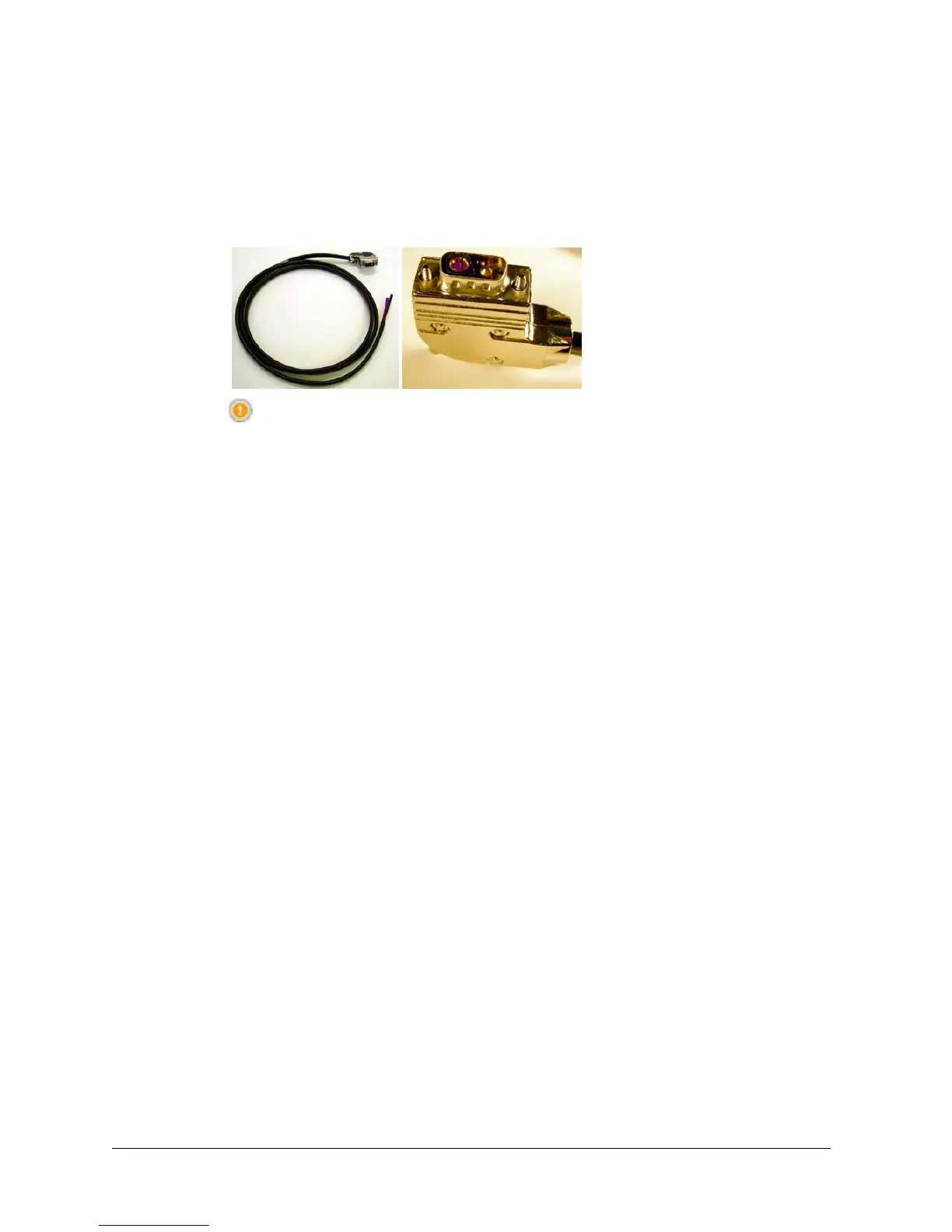
l A D-sub M/F 2W2 connector is fitted at one end, wire at the other.
l The cable is nominally 3m (10ft). The wires are 4mm2 (AWG12).
l The blue wire must be connected to live (-48 Vdc); the black wire to ground
(+48 Vdc).
Figure 1-6. Power Cable and Connector
CAUTION: Do not use the DC power connector as a power con-
nect/disconnect device. Always use the associated rack-mounted cir-
cuit breaker for this purpose.
Fuses
The chassis and PWR modules are fitted with a fast-acting 25A fuse. The fuse is not
field-replaceable.
Power Cable Installation
These steps describe the procedure for installing the power cable, in preparation for
power-on.
Do not connect the power cable to the CTR or to a PWR module until:
l CTR installation has been completed, with SD card, Fan module, and option
modules fitted.
l Management access has been prepared.
To install the power cable:
1. Run the supplied power cable through to a dedicated circuit breaker on the
rack power connect panel. The circuit breaker should have a 20A rating.
o
For back-up power using a PWR or PWR+AUX module, its power cable
must be to a separate dedicated circuit breaker. The circuit breaker should
have a 20A rating.
o
The circuit breakers are the power disconnect devices for the
CTR. Do not use the front-panel connectors for live power
connect/disconnect.
4. Trim to length, and connect the blue wire to -48Vdc (live), and the black
wire to ground/+ve. Trim the cable braid back to the cable sheath.
5. Measure the voltage on the dc power connector. The voltage should be -
48Vdc, +/-2Vdc for a non battery floated supply, and nominally -56 Vdc
for a battery floated supply. (Operational limits are -40.5 to - 57 Vdc).
10 AVIAT NETWORKS